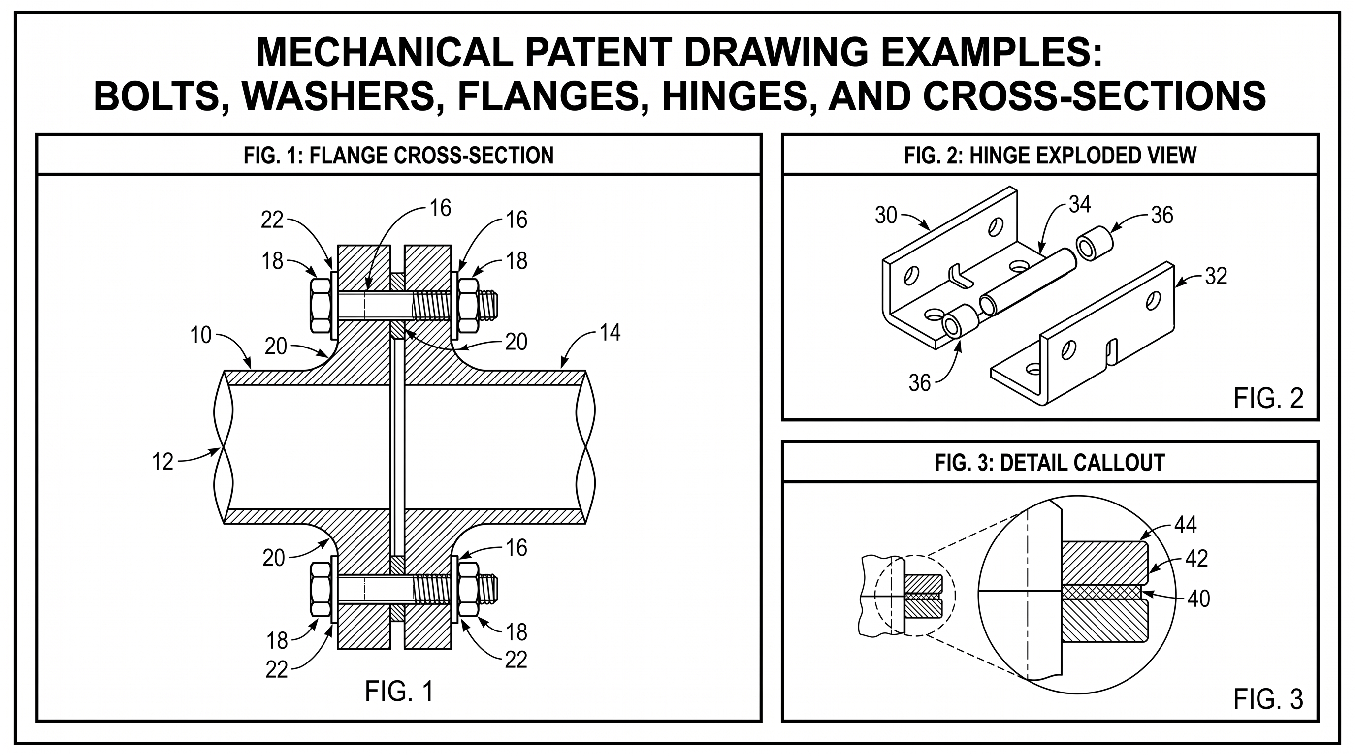
Mechanical Patent Drawing Examples: Bolts, Washers, Flanges, Hinges, and Cross-Sections
Practical mechanical patent drawing examples for bolts, washers, flanges, hinges, exploded views, cross-sections, labels, and revision workflows.
TL;DR: Mechanical patent figures fail on the small parts — an unnumbered washer, a gasket lost in hatching, an exploded view with an ambiguous assembly direction. Choose the figure type from the claim language first: cross-section for "disposed within" or "compressed between", exploded view for "removably coupled" or "inserted into", motion schematic for "pivoting" or "sliding". Then run a separate reference numeral pass so every claimed part is labeled consistently across views and matches the specification.
A mechanical figure can look clean and still fail the review. The bolt is visible, but the washer is not numbered. The flange is drawn, but the gasket is hidden by the hatching. The hinge is exploded, but the assembly direction is ambiguous. These are not artistic problems. They are communication problems.
Need compliant mechanical patent figures faster? Try PatentFig AI in the generator.
Mechanical patent drawings usually carry more burden than a single product image. They must show shape, relative position, functional relationships, and the parts that support the claims. For utility filings, the USPTO explains that drawings are required when needed to understand the claimed subject matter and points applicants to MPEP 608.02 and 37 CFR 1.84 for drawing standards. For international workflows, PCT Rule 11 is also worth checking because it is strict about reproducibility, drawing lines, hatching, lettering, and reference signs.
This guide is not legal advice. It is a practical drafting workflow for mechanical subject matter: bolts, washers, flanges, hinges, shells, gaskets, pistons, brackets, and similar assemblies.
If the figure set is for a utility filing, use the utility patent drawing generator as the broad entry point. Use the mechanical patent drawing generator for structures and cross-sections, and the exploded view patent drawing generator when assembly order matters.
Start With The Engineering Question
Do not start by asking for a beautiful patent drawing. Start by asking what the examiner, attorney, or reviewer needs to understand.
For a mechanical assembly, the useful question is usually one of these:
- What parts are present?
- How are the parts arranged?
- What part moves, seals, supports, locks, conducts, or releases?
- Which surfaces contact each other?
- Which feature is new compared with the surrounding conventional structure?
- Which part needs a reference numeral because the specification discusses it?
A flange assembly, for example, may need more than a front view. If the claim turns on a gasket, a sealant layer, a washer under a bolt head, or a leak path between pipe ends, a plain exterior view will hide the invention. A cross-section may be the primary figure, and a detail view may do more work than a polished perspective view.
Pick The Figure Type Before Drawing
Mechanical drawings become confusing when the figure type is chosen too late. Decide the purpose first, then generate the view.
| Figure type | Best for | Watch out for |
|---|---|---|
| Perspective view | Overall object recognition | Hidden internal features |
| Front or side view | External geometry and mounting points | Ambiguous depth |
| Exploded view | Assembly order and separable parts | Overcrowded arrows |
| Cross-section | Internal seals, bores, layers, channels | Hatching that obscures numerals |
| Detail view | Small washers, grooves, clips, ports | Losing context |
| Schematic view | Motion path, force path, fluid path | Looking too abstract |
PatentFig AI works best when you name the figure type directly. Instead of “draw a flange,” say “draw a cross-section of a flange assembly showing two pipe ends, flange rings, bolts, washers, and a gasket between the faces.” That instruction gives the image model a drafting job, not a vague design request.
Example: Flange, Bolts, Washers, And Gasket
The most common mechanical drawing issue is not missing the large component. It is missing the small part that matters. Washers, O-rings, grooves, spacers, clips, and gaskets are easy to lose when the model or drafter focuses on the main housing.
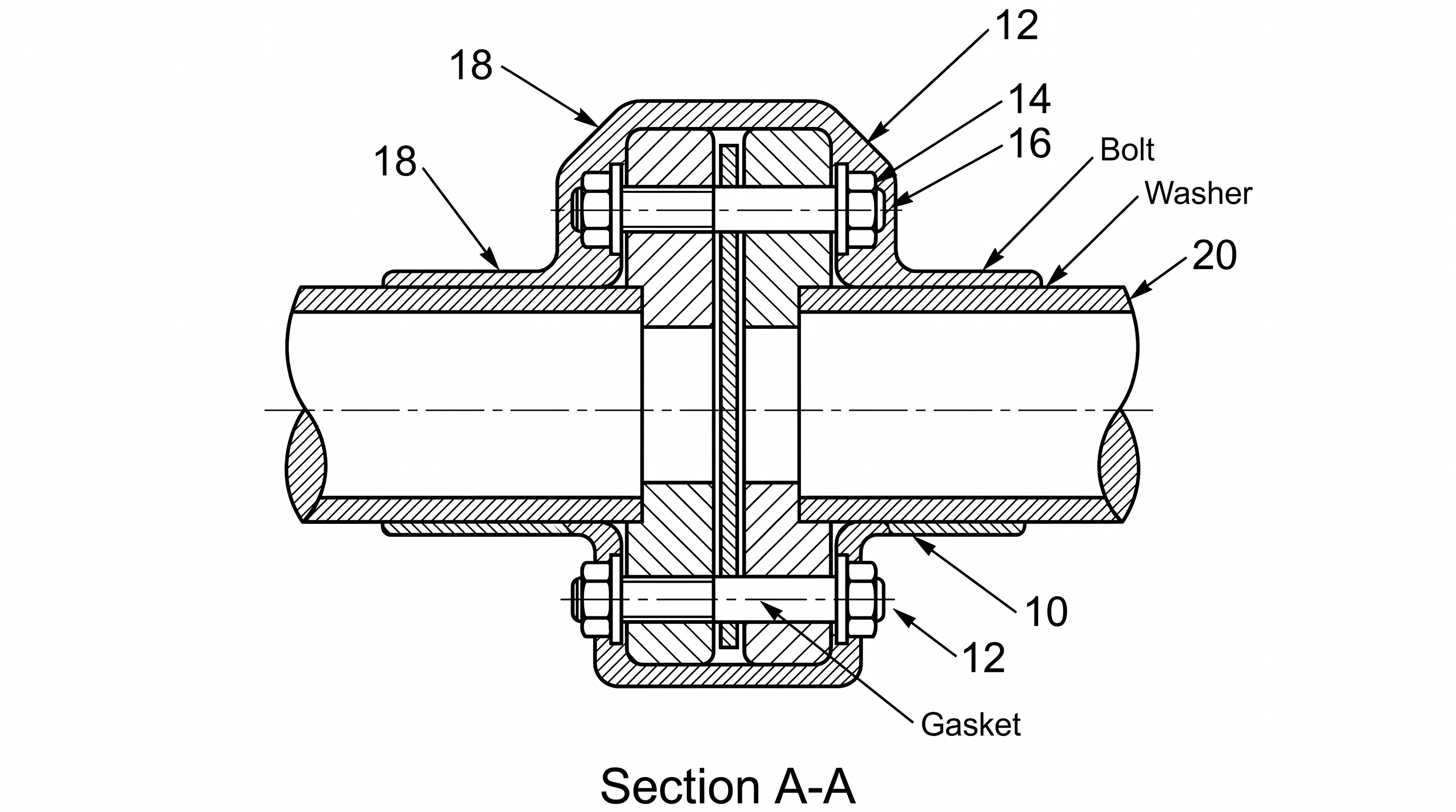
For a flange figure, separate the drawing into layers of meaning:
- Primary structure: pipe ends, flange rings, mating faces.
- Fastening structure: bolts, nuts, washers, spacers.
- Sealing structure: gasket, sealant, O-ring, compression surface.
- Functional path: fluid path, leak path, load path, monitoring path.
- Reference system: numerals, leader lines, and figure labels.
If the washer is claimed, it should not be visually merged into the bolt head. If the gasket is claimed, it should not disappear into the flange face. If a protective coating or gel layer is claimed, it should be visually distinct without becoming decorative shading.
Useful prompt pattern:
Create a black-and-white mechanical patent drawing, FIG. 2, showing a flange assembly in cross-section. Show two pipe ends, opposed flange rings, bolts passing through the flange rings, washers under the bolt heads, and a gasket between the flange faces. Use oblique hatching only for sectioned material. Add straight leader lines and reference numerals for pipe end, flange ring, bolt, washer, gasket, and sealing interface. Do not add unsupported parts.The last sentence matters. Mechanical users often want the model to preserve the disclosed structure and avoid inventing extra fasteners, sensors, covers, or decorative elements.
Exploded View Or Cross-Section?
Use an exploded view when the reader needs to understand how parts separate or assemble. Use a cross-section when the reader needs to understand what happens inside the object.
For a hinge, an exploded view can show a pin, knuckles, spring, bracket, and cover plate. For a piston stopper, a cross-section may be better because the important features are the bore, chamfer, O-ring groove, and sealing surface. For a clamshell housing, you may need both: an open perspective view for the bivalved configuration and a cross-section for interior apertures.
The drafting test is simple:
- If the claim uses words like “disposed within,” “received in,” “compressed between,” or “fluidly connected,” consider a cross-section.
- If the claim uses words like “removably coupled,” “assembled with,” “inserted into,” or “attached to,” consider an exploded view.
- If the claim uses words like “pivoting,” “rotating,” “sliding,” or “folding,” consider a motion schematic in addition to the structural view.
Reference Numerals Need Their Own Pass
Do not treat labels as decoration. A mechanical figure can be structurally correct and still be weak if the numbering is inconsistent.
Run a separate reference numeral pass:
- Does every numeral appear in the specification?
- Does every important claimed feature have a numeral?
- Are the same features numbered the same way across figures?
- Are leader lines straight and unambiguous?
- Do leader lines point to the part edge rather than floating near it?
- Are small parts like washers, clips, and grooves labeled without crowding?
- Are numbers readable after export?
PCT Rule 11 is especially useful as a conservative baseline because it emphasizes clear reference signs, uniform lines, and cross-section hatching that does not interfere with reference signs and leading lines. Even if you are not filing PCT, those principles are good drafting discipline.
A Practical Mechanical Figure Workflow
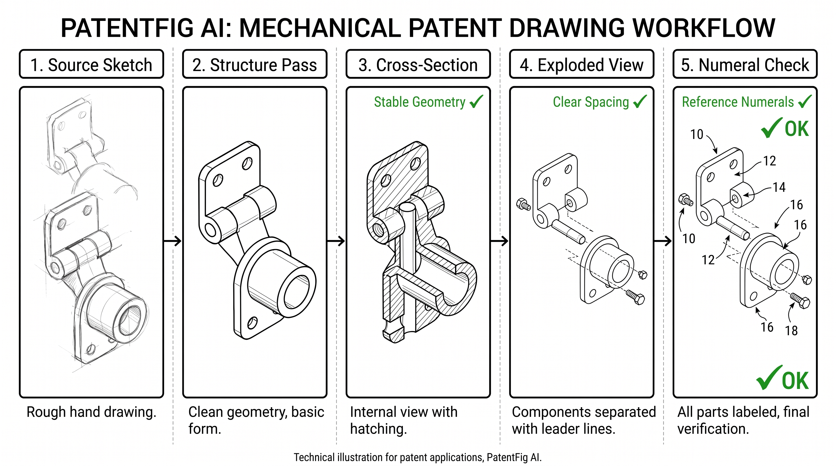
Use this workflow when turning a sketch, photo, CAD screenshot, or written disclosure into patent figures:
- Name the object and invention focus. Example: “flange monitoring assembly with protective gel layer and leak indicator.”
- List the required parts. Include small parts such as washers, O-rings, spacers, ports, grooves, and caps.
- Choose the figure set. Start with one overview, one cross-section, one detail or exploded view.
- Generate a first draft. Use black-and-white line art, no color, no gradient, no product branding.
- Review structure before labels. Fix missing parts before adding numerals.
- Add numerals and leader lines. Keep numbering stable across figures.
- Run a pre-submission drawing check. Look for margins, line clarity, hatching, crowded labels, and export format.
The order matters. If you add numerals before the structure is stable, every later geometry edit can break the label map.
Prompt Template For Mechanical Patent Figures
Use this as a starting point:
Create a professional black-and-white mechanical patent drawing for [object]. Figure type: [perspective / exploded / cross-section / detail / schematic]. Show these parts only: [part list]. The invention focus is [specific relationship or feature]. Use clean uniform line work, straight leader lines, readable reference numerals, and minimal hatching only where needed. Preserve the disclosed geometry. Do not add decorative styling, shading, unsupported components, logos, or background objects.For revisions, be even more specific:
Keep the existing geometry unchanged. Add reference numeral 16 to the washer under the bolt head and numeral 18 to the gasket between the flange faces. Do not redraw the flange rings, do not add new bolts, and do not change the cross-section hatching.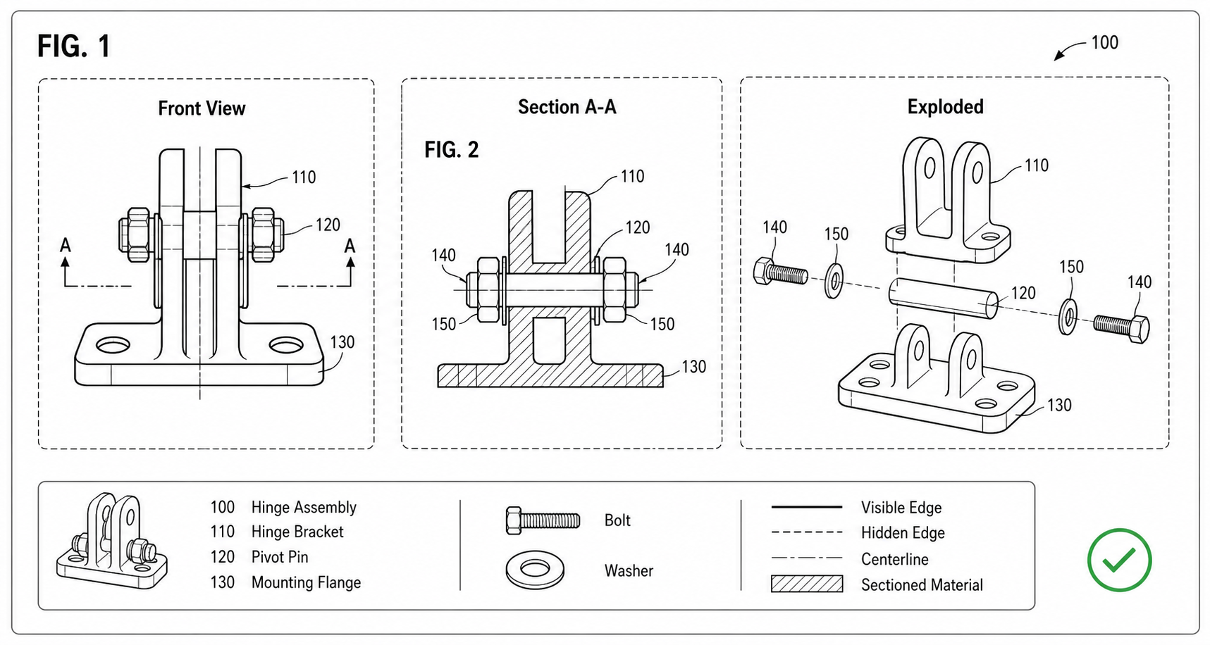
That is the kind of instruction PatentFig AI is designed to handle: targeted mechanical revision without restarting the whole drawing.
How Different Teams Should Use This
Patent attorneys should use the checklist to verify support in the specification. If a part is shown but not described, or described but not shown, resolve that before filing.
Patent engineers should provide the part list, view choice, and “do not invent” constraints. The more explicit the component relationships are, the better the first draft.
Operations teams should track revision causes. If every mechanical figure needs three rounds of “label the small part,” build a standard part list template before generating.
Create Mechanical Patent Figures Faster
Ready to turn mechanical sketches, CAD screenshots, or part descriptions into patent-ready visuals? Open the PatentFig AI generator.
Next step: Browse the mechanical patent drawing examples — or open the generator and adapt the closest one to your invention.
Author

Categories
More Posts
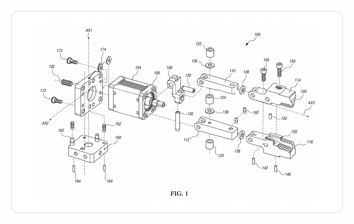
Exploded View Patent Drawing Workflow: Parts, Spacing, Callouts, and Review
Plan exploded view patent drawings with clear part order, spacing, leader lines, reference numerals, and pre-export review.
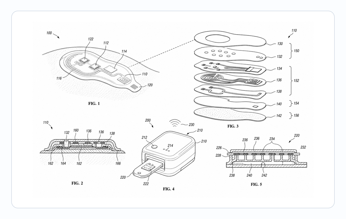
Medical Device Patent Figures: Exploded Views, Cross-Sections, and Use States
Plan medical device patent figures for cartridges, wearables, patches, sensors, surgical tools, exploded views, cross-sections, and use states.
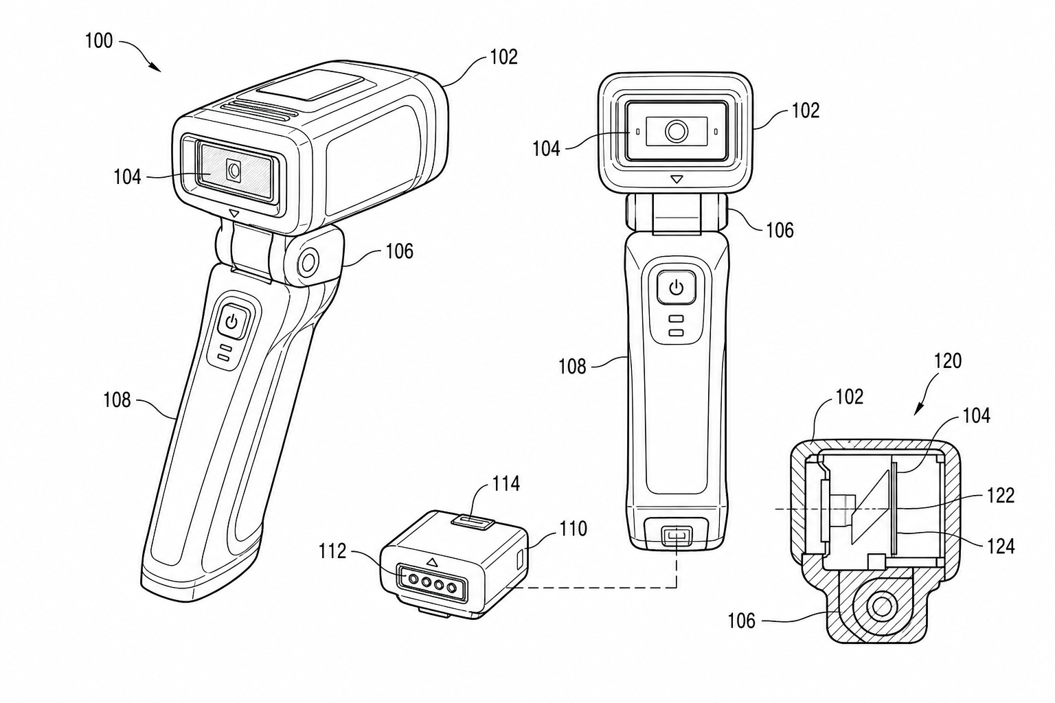
Utility Patent Drawings vs Design Patent Drawings: Which Figures You Need
Compare utility patent drawings and design patent drawings: figure purpose, views, line rules, broken lines, reference numerals, and when to use each workflow.
Newsletter
Join the community
Subscribe to our newsletter for the latest news and updates