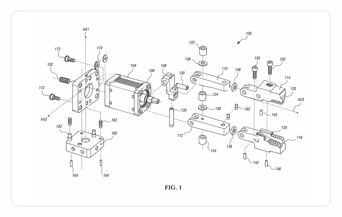
Exploded View Patent Drawing Workflow: Parts, Spacing, Callouts, and Review
Plan exploded view patent drawings with clear part order, spacing, leader lines, reference numerals, and pre-export review.
TL;DR: Use an exploded view when the claim depends on how parts separate, align, attach, lock, or seal; pick a single separation axis, keep spacing even, and verify every leader line lands on the correct part. Every numbered component must map to the disclosure — and when the key relationship is hidden inside the assembly, a cross-section is usually the better figure.
A clean exploded view can save a reviewer from reading three paragraphs of part relationships. A messy exploded view does the opposite: parts float without order, leader lines cross, and the drawing starts to look like a product manual instead of a patent figure.
Use the exploded view patent drawing generator when the invention depends on components that separate, align, attach, lock, seal, or replace each other.
When An Exploded View Is The Right Figure
Choose an exploded view when the reader needs to see assembly logic. Good candidates include housings, cartridges, brackets, fastener stacks, hinges, caps, covers, sensor modules, filter assemblies, and medical consumables.
Do not use an exploded view just because it looks technical. If the important feature is hidden inside a bore, channel, gasket, or layered material, a cross-section may carry the claim support better. Many strong figure sets use both: one exploded view for assembly order and one cross-section for internal relationships.
Prepare The Source Before Generating
Before drafting, write a short part list. Include the large parts and the small parts that are easy to lose: washers, clips, seals, spacers, springs, ports, pins, adhesive layers, and covers. Then decide which parts should separate in the figure and which should stay assembled.
| Item | Review question |
|---|---|
| Main body | Is the orientation clear? |
| Removable module | Does the separation direction match the disclosure? |
| Fastener or clip | Is it visible enough to receive a numeral? |
| Seal or gasket | Should it appear in the exploded view, cross-section, or both? |
| Alignment feature | Does the drawing show how parts fit together? |
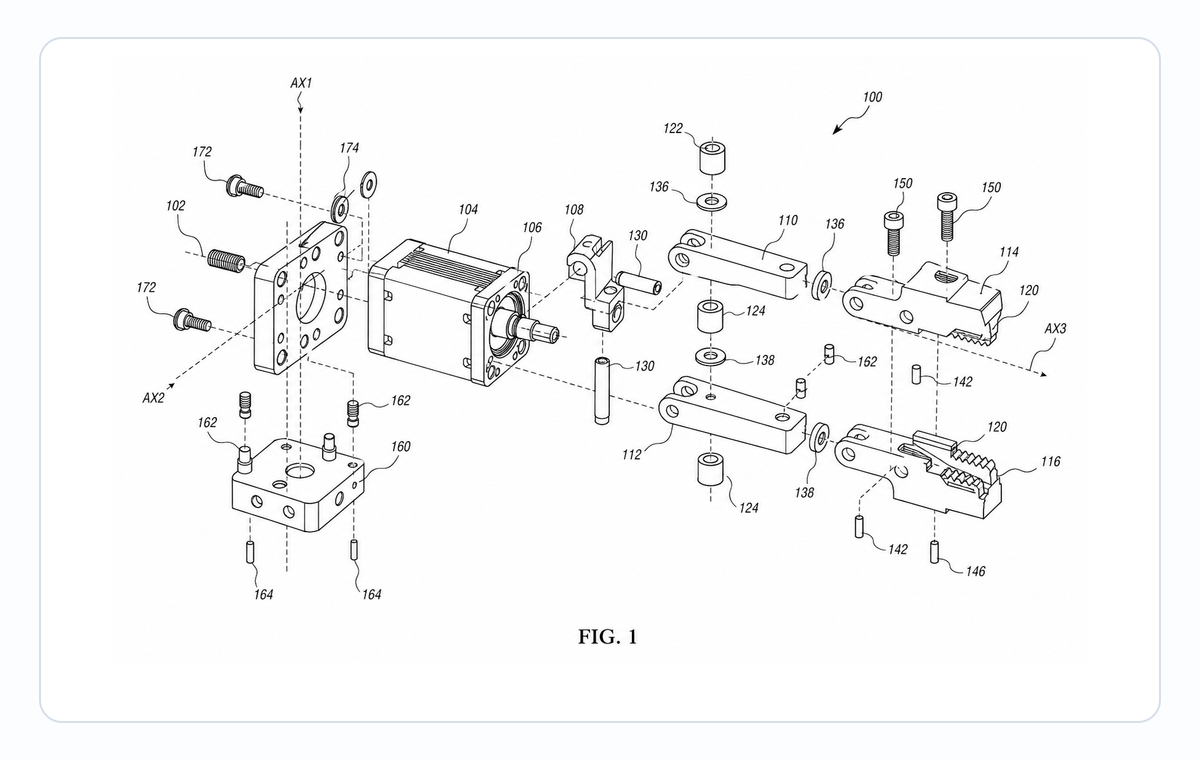
Drafting Workflow
Start with a product photo, CAD view, sketch, or written disclosure. List the required parts and the parts that must not be invented. Generate the exploded arrangement with clean black line work. Review spacing before adding many labels. Add reference numerals only after the part positions are stable.
Prompt Template
Create a black-and-white exploded patent drawing of [assembly]. Show these parts only: [part list]. Separate the parts along the assembly axis, keep alignment clear, use uniform line work, and add readable reference numerals with straight leader lines. Do not add unsupported components, branding, texture, color, or decorative shading.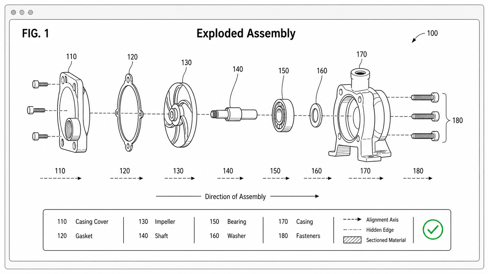
Pick One Separation Axis
The single biggest cause of unreadable exploded views is parts flying apart in three or four different directions on the same page. Pick one separation axis — vertical for stacked components, horizontal for serial assemblies, radial for parts that fan out from a central body — and apply it consistently. If two assemblies genuinely need different axes (a stacked cartridge plus a hinged cover), they belong on two figures, not one crowded sheet.
The axis decision also drives the page orientation. Vertical separation usually wants a portrait sheet; horizontal separation usually wants landscape. Confirm the orientation before populating the figure, because rotating after labels are placed forces a leader-line rework.
Spacing and Leader Lines
Exploded views fail at the leader stage more often than at the geometry stage. Three working rules:
- Gap between parts must exceed the diameter of the largest reference numeral. Smaller gaps make numerals collide with adjacent parts.
- Leader lines should be straight or at most one bend. Curved leaders or multiple bends look like arrows for assembly direction, which confuses the reader.
- Alignment hairlines, when used, must be dashed. A solid alignment line reads as a structural feature. A dashed line reads as a guide.
A practical layout pattern: place the central body in the middle, separated parts above and below (or left and right depending on axis), and reserve a 1.5 cm strip on the right margin for reference numerals so leaders stay short.
Common Mistakes by Category
| Category | Mistake | Fix |
|---|---|---|
| Direction | Parts separate in two or three axes on one figure | Pick one axis; split if needed |
| Spacing | Parts so tight that leaders collide | Increase gaps; allow whitespace |
| Numerals | Same numeral used in exploded view and the cross-section for different parts | Maintain a single numeral table |
| Alignment | Solid alignment lines mistaken for structural features | Use dashed lines for alignment guides |
| Hidden parts | Internal seals or O-rings shown floating with no destination | Move to a cross-section instead |
| Branding | Logo, brand text, or material callout left in the figure | Strip before export |
| Scale | One part drawn at a different scale than the rest | Match scale across the figure |
Exploded View vs Cross-Section — Decision Table
The two view types overlap in some cases. When you can pick only one:
| Aspect | Exploded view | Cross-section |
|---|---|---|
| Best at | Assembly order, separable parts, fastener stacks | Internal channels, layered material, seal positions |
| Reference numerals | Many, spread across parts | Fewer, focused on internal features |
| Reader effort | Lower — relationships are visual | Higher — readers must understand the cut plane |
| Risk if misused | Becomes a parts catalog | Becomes a fabrication blueprint |
| Often paired with | A perspective overview | An overview showing the cutting plane |
For an assembly that needs both, draft the exploded view first, then add a cross-section through the most claim-relevant region. Both figures should share the same overview, the same reference numerals, and the same scale.
Per-Office Notes
USPTO MPEP 608.02(VII) explicitly accepts exploded views and treats them as ordinary patent figures. PCT Rule 11.6 does not single them out; the same uniform line-work rules apply. EPO Rule 46 EPC is the same.
CNIPA has historically been stricter about labeling: every separated part needs a reference numeral, and the assembly direction should be implied by the layout, not by added arrows. JPO accepts arrow-based assembly direction indicators but they should be subtle (dashed, not bold). KIPO follows JPO convention.
If the application is heading to multiple jurisdictions, draw without assembly arrows. A clean axial layout reads as "assembly direction" without needing arrows that might be cited differently across offices.
Review Before Export
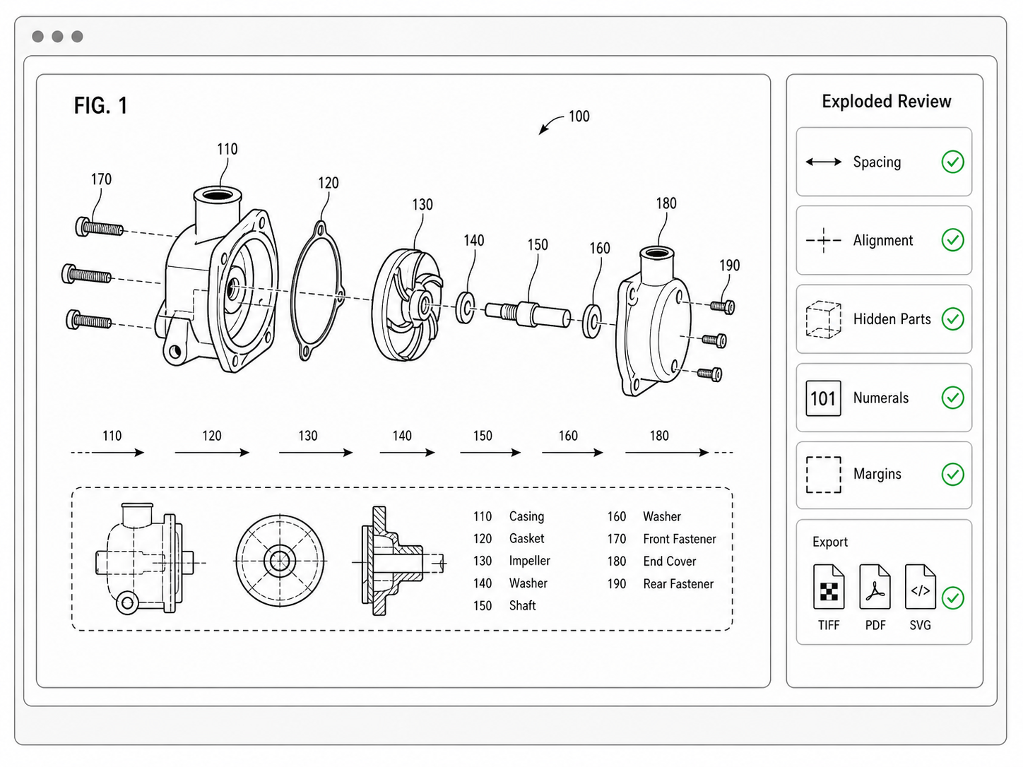
Before export, ask four questions: does the exploded view explain assembly order? Does every numbered part map to the disclosure? Would a separate cross-section make the hidden relationship clearer? Has every leader line been verified to end on the right part?
When the answer is stable, continue to Figure Checker or open the PatentFig AI generator.
Next step: Open the generator and try this workflow with your own source material — or browse patent drawing examples for a starting point.
Author

Categories
More Posts
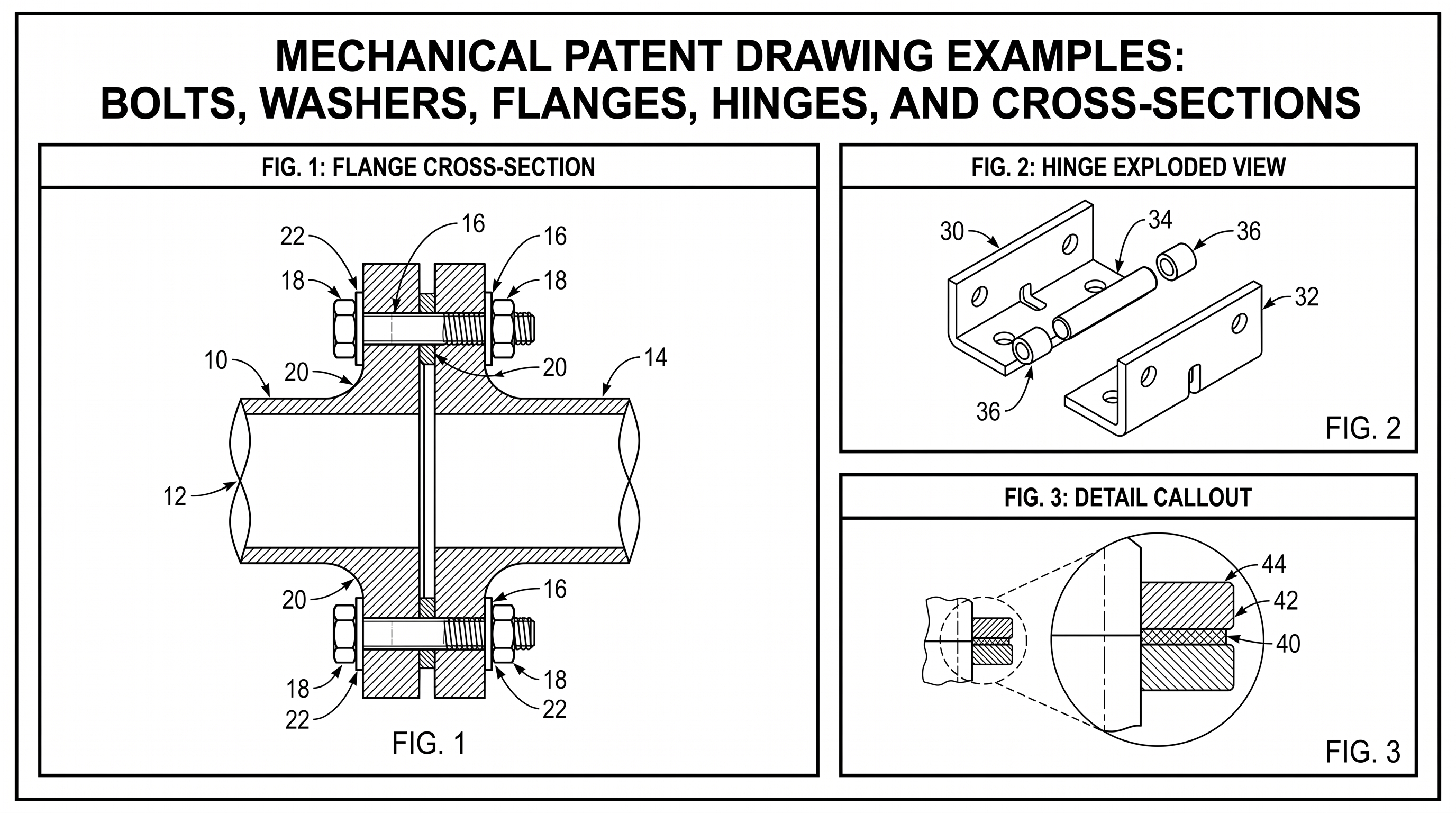
Mechanical Patent Drawing Examples: Bolts, Washers, Flanges, Hinges, and Cross-Sections
Practical mechanical patent drawing examples for bolts, washers, flanges, hinges, exploded views, cross-sections, labels, and revision workflows.
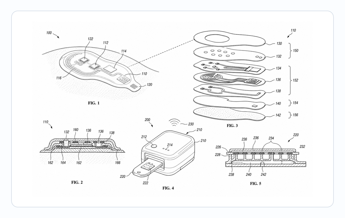
Medical Device Patent Figures: Exploded Views, Cross-Sections, and Use States
Plan medical device patent figures for cartridges, wearables, patches, sensors, surgical tools, exploded views, cross-sections, and use states.
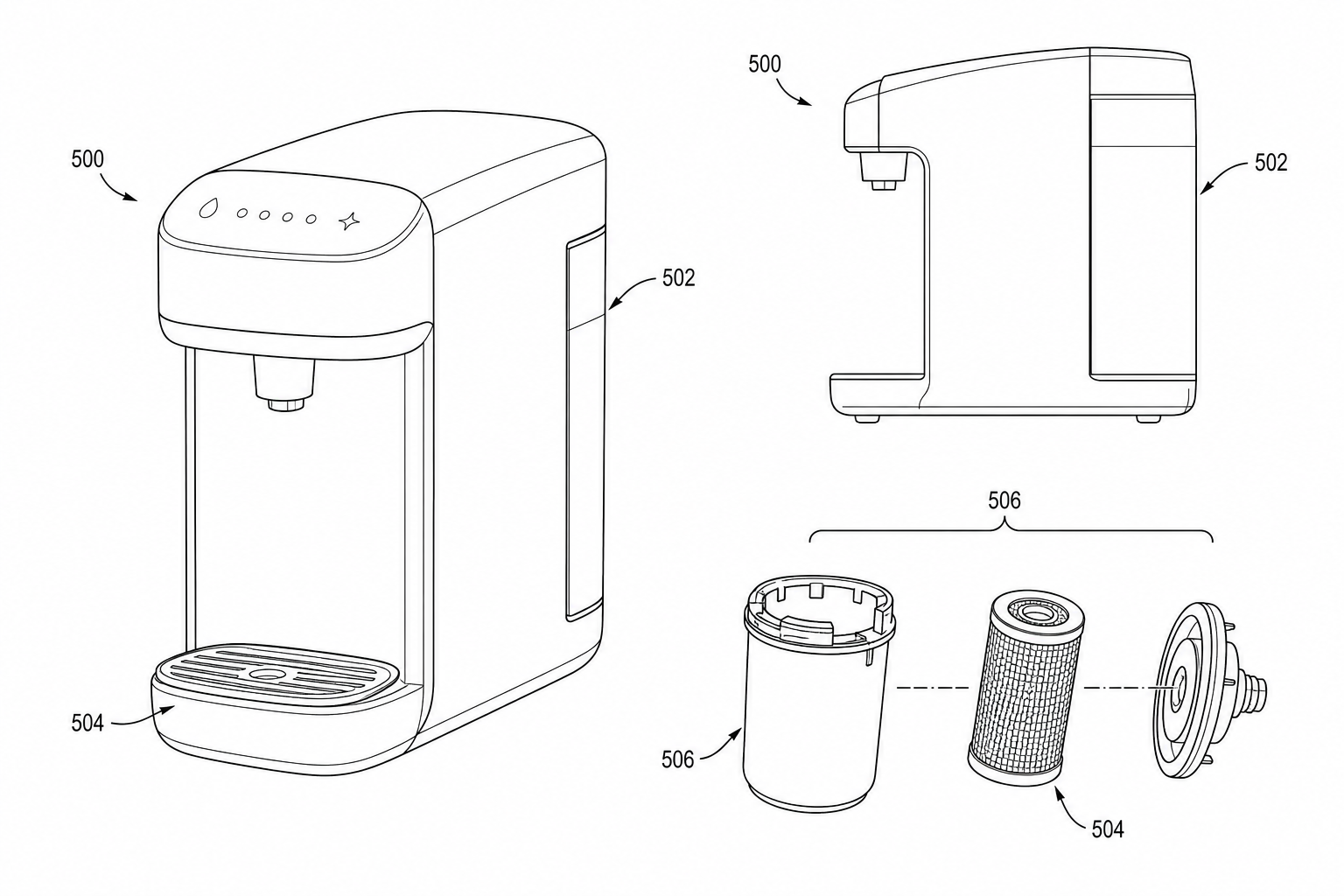
Product Photo to Patent Line Art: When AI Works and When to Redraw
Learn when product photos can be converted into patent line art with AI, when manual redraw is safer, and how to prepare views for patent filing.
Newsletter
Join the community
Subscribe to our newsletter for the latest news and updates