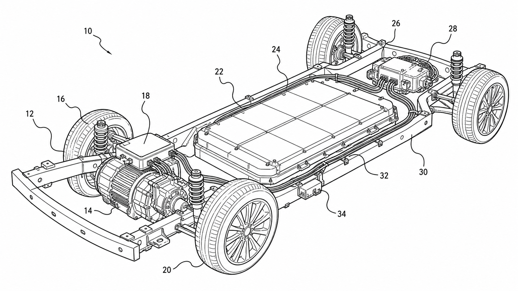
Automotive Patent Drawings: Powertrain, EV Battery Packs, ADAS, and Wiring Harnesses
A practical guide to automotive patent drawings: which figure type supports which claim across powertrain, EV battery packs, ADAS, and wiring harnesses.
TL;DR: Automotive inventions span mechanical, electrical, and software claims in a single filing, so the figure set has to do the same. Match each claim to its native figure type — cross-sections for powertrain structure, exploded views for battery packs, layout plus block diagrams for ADAS, routing schematics for harnesses — and keep one numeral pointing to one part across the whole set.
Few technical fields stretch a patent drawing set the way automotive does. One application can claim a planetary gearset, a liquid-cooled battery module, a sensor-fusion pipeline, and a wiring harness clip in the same breath. Each of those wants a different kind of figure, and a reviewer should never have to guess which figure supports which claim. This guide walks through the major automotive figure types by claim, the office rules that govern them, and the mistakes that trigger drawing objections.
Start from the automotive patent drawings page when your source is a vehicle subsystem and you need a full, consistent figure set rather than one isolated view.
Powertrain and Drivetrain: Cross-Sections Carry the Claim
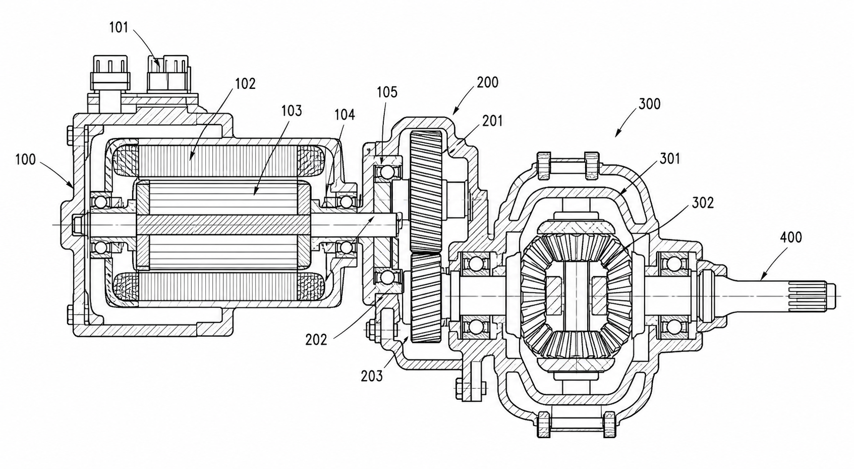
Powertrain novelty almost always lives inside the housing — in how a rotor sits relative to a stator, how a gearset transfers torque, how a clutch pack engages, or how a cooling jacket wraps a motor. None of that is visible from the outside, so a perspective view alone will not support a structural claim. The workhorse here is the cross-section.
A good powertrain cross-section is black-and-white line art taken along a clearly indicated section plane. Show the section line and arrows on a companion view so the reader knows exactly where the cut was taken. Inside the section, hatching distinguishes solid material from voids and oil galleries, and each claimed feature — bearing seat, oil channel, spline, seal land — gets a reference numeral placed outside the part with a clean squiggly lead line pointing in.
For an integrated e-axle, a typical set looks like this:
- Fig. 1 — perspective or side view of the complete drive unit, establishing orientation and the section line.
- Fig. 2 — longitudinal cross-section through the motor shaft showing rotor, stator, bearings, and the reduction gearset.
- Fig. 3 — transverse cross-section through the gearbox showing gear mesh and the differential.
- Fig. 4 — detail/enlarged view of the cooling jacket or oil-spray path if that is claimed.
Use the mechanical patent drawing generator when the claim is structural and you need section views, hatching, and lead lines that follow drawing-office conventions rather than CAD defaults.
When to add an exploded view to a powertrain set
If a claim covers assembly order, modularity, or how a unit is serviced — say, a motor that drops out without disturbing the gearbox — an exploded view earns its place alongside the cross-section. The cross-section proves the internal geometry; the exploded view proves the assembly relationship.
EV Battery Packs: Exploded Views Show the Stack
Battery-pack claims are overwhelmingly about arrangement: how cells are grouped into modules, how cooling plates interleave with cells, how busbars connect terminals, and how the housing seals and protects the stack. That is exactly what an exploded view is built to show.
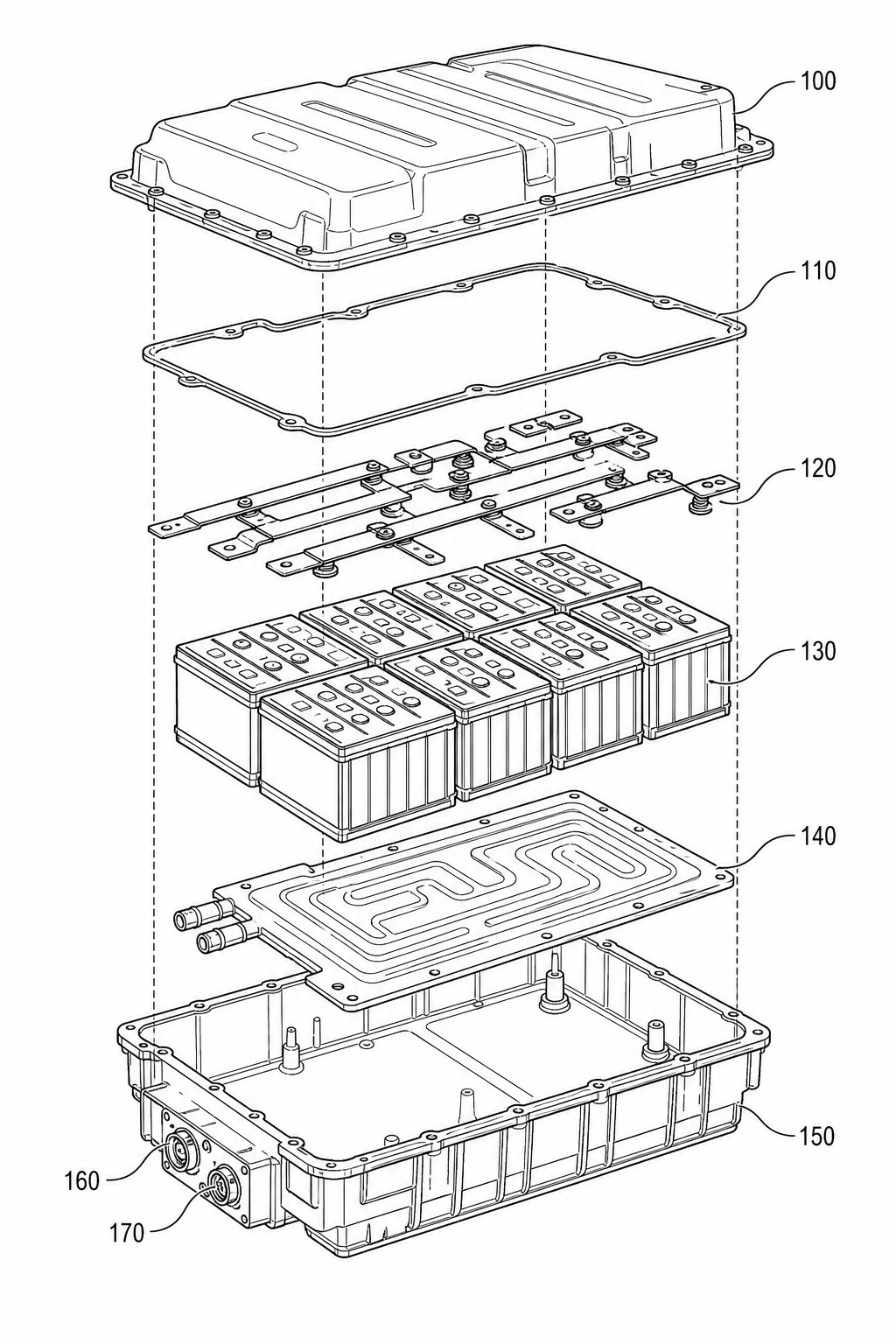
Draw the pack as a vertical or diagonal stack with components separated along dash-dot alignment axes so the reader can read assembly order at a glance: lower housing, cooling plate, cell modules, busbar layer, BMS board, compression frame, upper cover. Keep the parts on a pure white background with no shading, no gradients, and no drop shadows — just clean outlines. The exploded view patent drawing generator is the right starting point when stacking order or serviceability is the claimed feature.
A practical battery figure set:
| Figure | What it shows | Claim it supports |
|---|---|---|
| Exploded view | Full stack: housing, cells, cooling plate, busbars, cover | Cell arrangement, module grouping, assembly order |
| Cross-section | Cut through a module and cooling plate | Internal cooling channels, thermal interface, spacing |
| Top plan view | Cell layout and busbar routing across the pack | Electrical interconnection topology |
| Detail view | Single cell-to-busbar joint or vent path | A specific connection or safety-vent feature |
A common error is drawing every cell in a 100-cell module individually. You do not need to. Show a representative group, label it once, and let the written disclosure state the count. Over-drawing a battery figure makes it crowded and harder to number consistently.
ADAS: Layout View Plus Sensor-Fusion Block Diagram
ADAS inventions are split-personality cases — part physical placement, part data processing — and they need two distinct figures to cover both.
The first is a top-view (plan) layout of the vehicle showing where each sensor sits and what it watches: forward radar in the grille, a windshield camera, corner radars, side cameras, and surround ultrasonic sensors. Indicate each sensor's detection zone with a labeled field-of-view region so a placement claim ("a radar mounted to scan a forward zone overlapping the camera field of view") has direct figure support.
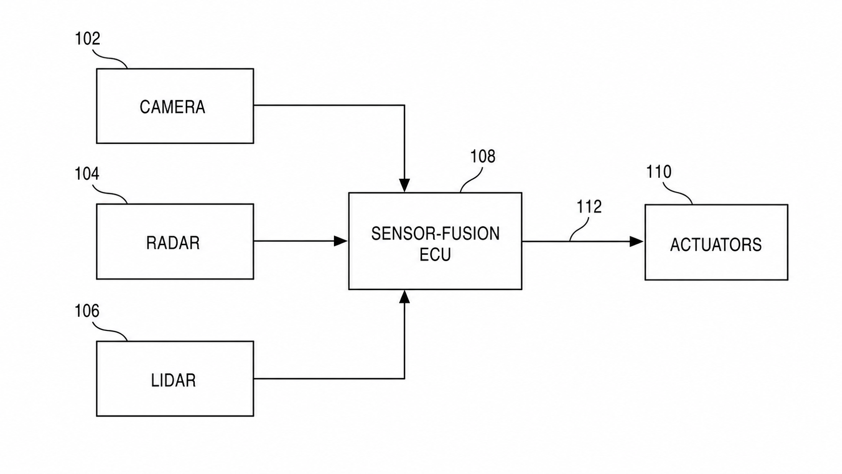
The second is a sensor-fusion block diagram. This is where most ADAS claims actually live: how raw sensor streams are pre-processed, time-aligned, and combined in a fusion module, then passed to perception, planning, and a vehicle-control output. Draw each claimed stage as its own labeled block with arrows showing data flow. Keep block names short and technical — "radar preprocessing," "object fusion," "trajectory planner" — not marketing phrases. Because this figure is a schematic rather than a structural drawing, the electrical patent diagram generator is the natural fit.
A clean ADAS pair reads like this:
- Layout view: answers where are the sensors and what do they see.
- Block diagram: answers how does sensor data become a control decision.
If a claim recites a fail-operational fallback or a redundant sensing path, make that path explicit in the block diagram with its own branch — do not bury it inside a single "controller" box.
Wiring Harnesses: Routing Schematics, Not Photographs
Harness claims usually concern routing, branch points, connector positions, retention clips, or shielding. The figure that supports them is a routing schematic: a simplified vehicle or panel outline with the harness drawn as line work, branch points marked, and connectors and clips called out with numerals.
Two figure styles cover most harness filings:
- Routing diagram — the harness laid over a vehicle or chassis outline, showing the main trunk, branches, and where each branch terminates. This supports claims about routing path and clip placement.
- Connector/pin detail — an enlarged view of a specific connector or splice if the claimed feature is the connection itself.
Resist the urge to paste in a photograph of a real loom. Photographs carry shading and clutter that violate the line-art requirement, and the dozens of nearly identical wires make numbering hopeless. A schematic with a representative set of conductors is both compliant and clearer. For the connection logic — what wire ties to what node — pair the routing view with a block or wiring diagram from the electrical patent diagram generator.
Suspension and Chassis: Show the Multiple States
Suspension and steering claims often hinge on motion — a linkage that moves between compressed and extended positions, or a steering knuckle that articulates through a range. A single static view cannot prove a motion claim.
The convention is to show the mechanism in multiple states: draw the primary position in solid lines and the alternate position in broken (phantom) lines on the same figure, or provide two side-by-side figures (Fig. 5A compressed, Fig. 5B extended). Phantom-line overlays are compact and make the range of motion obvious; separate figures are clearer when the geometry change is large. Either way, the moving part keeps the same reference numeral in every state so the reader tracks it across positions. This is squarely mechanical work — use the mechanical patent drawing generator for multi-state linkage figures.
The Office Rules That Apply to All of These
Across powertrain, battery, ADAS, harness, and chassis figures, the same baseline rules from USPTO 37 CFR §1.84 govern the drawings, and CNIPA, the EPO, and the JPO impose closely parallel requirements:
- Black-and-white line art with solid, uniformly thick lines. No color, no grayscale shading, no photographs unless a photo is the only practical way to show the subject.
- Pure white background. No gradients, textures, or borders around the drawing area.
- Reference numerals placed outside the part, each connected by a squiggly lead line that touches but does not cross the part it identifies. Numerals should not sit on hatched or busy areas where they become unreadable.
- Consistent line weight between feature lines and lead lines, with lead lines typically lighter so they read as references, not structure.
- Section lines and view indicators so cross-sections and detail views tie back to the parent figure.
CAD exports tend to violate the first two by default — they arrive shaded, anti-aliased, and on a gray background. Converting those into compliant line art is a routine step, not an optional polish; PatentFig AI's convert, enhance, and vectorize tools exist precisely for that hand-off.
Automotive-Specific Mistakes to Avoid
- Shaded CAD renderings submitted as-is. The single most common automotive objection. Solid models look impressive and fail the line-art rule.
- Drawing every identical cell, bolt, or wire. Crowds the figure and makes numbering unmanageable. Show a representative element and state quantities in text.
- One mega-figure for an entire subsystem. Trying to cram the whole powertrain or full ADAS stack into one drawing produces unreadable clutter. Split by claim.
- Static figures for motion claims. Suspension and steering claims need multi-state views; a single position does not support a range-of-motion limitation.
- Marketing labels in block diagrams. "Smart fusion engine" is not a claim term. Use the technical name the claims use.
- Photographs of harnesses or engine bays. Clutter plus shading equals an objection, and the parts cannot be cleanly numbered.
Numeral Consistency Across a Large Figure Set
This is the discipline that separates a clean automotive filing from a messy one. A vehicle application can run to 30 or more figures sharing the same parts — the same housing appears in a perspective view, a cross-section, and an exploded view. The rule is simple and unforgiving: one numeral maps to exactly one part, and one part keeps the same numeral everywhere it appears.
Practical workflow:
- Build a numeral table first. Before drawing, list every part and assign each a single numeral (motor housing = 10, stator = 12, rotor = 14, and so on). Leave gaps so you can insert later parts without renumbering.
- Reuse, never re-mint. When the housing reappears in Fig. 7, it is still 10 — not a fresh number for the same part.
- Watch the cross-references. The body text and claims must use the same numerals as the drawings. A numeral the spec never mentions, or a spec numeral missing from the drawings, both draw scrutiny.
- Run the full set through a checker before filing. With dozens of figures, manual proofreading misses collisions — two parts sharing a number, or a number that points to two different parts in different figures.
PatentFig AI keeps a shared numeral map across a multi-view set, so generating a cross-section and an exploded view of the same assembly reuses the same numerals automatically, and the figure checker flags collisions before export.
How PatentFig AI Helps
PatentFig AI turns a vehicle subsystem — described in text, sketched, or supplied as a 3D model — into a complete, office-ready figure set: cross-sections for powertrain structure, exploded views for battery packs, layout and block diagrams for ADAS, routing schematics for harnesses, and multi-state views for suspension. It outputs compliant black-and-white line art on a pure white background, holds reference numerals consistent across the whole set, lets you refine any figure by chat-to-modify editing, and runs the set through a figure checker for 37 CFR §1.84 and CNIPA compliance before you file. Convert, enhance, and vectorize tools handle the CAD-to-line-art hand-off.
Open the generator and try it with your own automotive subsystem — or browse the automotive patent drawings page for a starting point.
Author

Categories
More Posts
Medical Device Patent Drawing Checklist: Catheters, Stents, Implants, and Auto-Injectors
A practical medical device patent drawing checklist plus reusable prompt templates for use-states, cross-sections, and exploded auto-injector assemblies.
Circuit Patent Drawing Examples for Utility Patent Applications
Examples of circuit patent drawings for signal paths, sensor circuits, control loops, power routing, and functional blocks in utility patent filings.
Electrical Patent Drawings: Patent Figure vs Engineering Schematic
Electrical patent drawings should explain invention relationships, not replace engineering schematics. Learn how to draw power paths, sensors, control signals, and system blocks.
Newsletter
Join the community
Subscribe to our newsletter for the latest news and updates