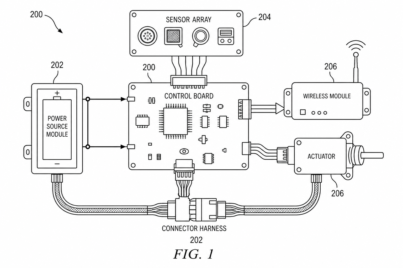
Electrical Patent Drawings: Patent Figure vs Engineering Schematic
Electrical patent drawings should explain invention relationships, not replace engineering schematics. Learn how to draw power paths, sensors, control signals, and system blocks.
TL;DR: An electrical patent figure and an engineering schematic are different documents: the patent figure shows the claimed relationships (power source, controller, sensors, load, signal direction, fault handling), while the schematic carries part numbers, component values, and layout details for manufacturing. Strip everything the claim does not need, and use three figures — a system block diagram, a power/signal routing figure, and a control flowchart — instead of pasting a dense EDA schematic.
Electrical inventions often begin with engineering source material: schematics, wiring sketches, PCB screenshots, or power-routing notes. Those sources are useful, but they are usually too detailed for a patent figure. A reviewer needs to see the invention relationship quickly, not decode every component in the engineering file.
For a patent application, redraw the source as a relationship diagram: which parts receive power, which parts sense signals, how the controller makes decisions, and how the load or communication module responds. The electrical patent diagram generator can draft that relationship figure; circuit performance, safety, and manufacturability still need engineering review.
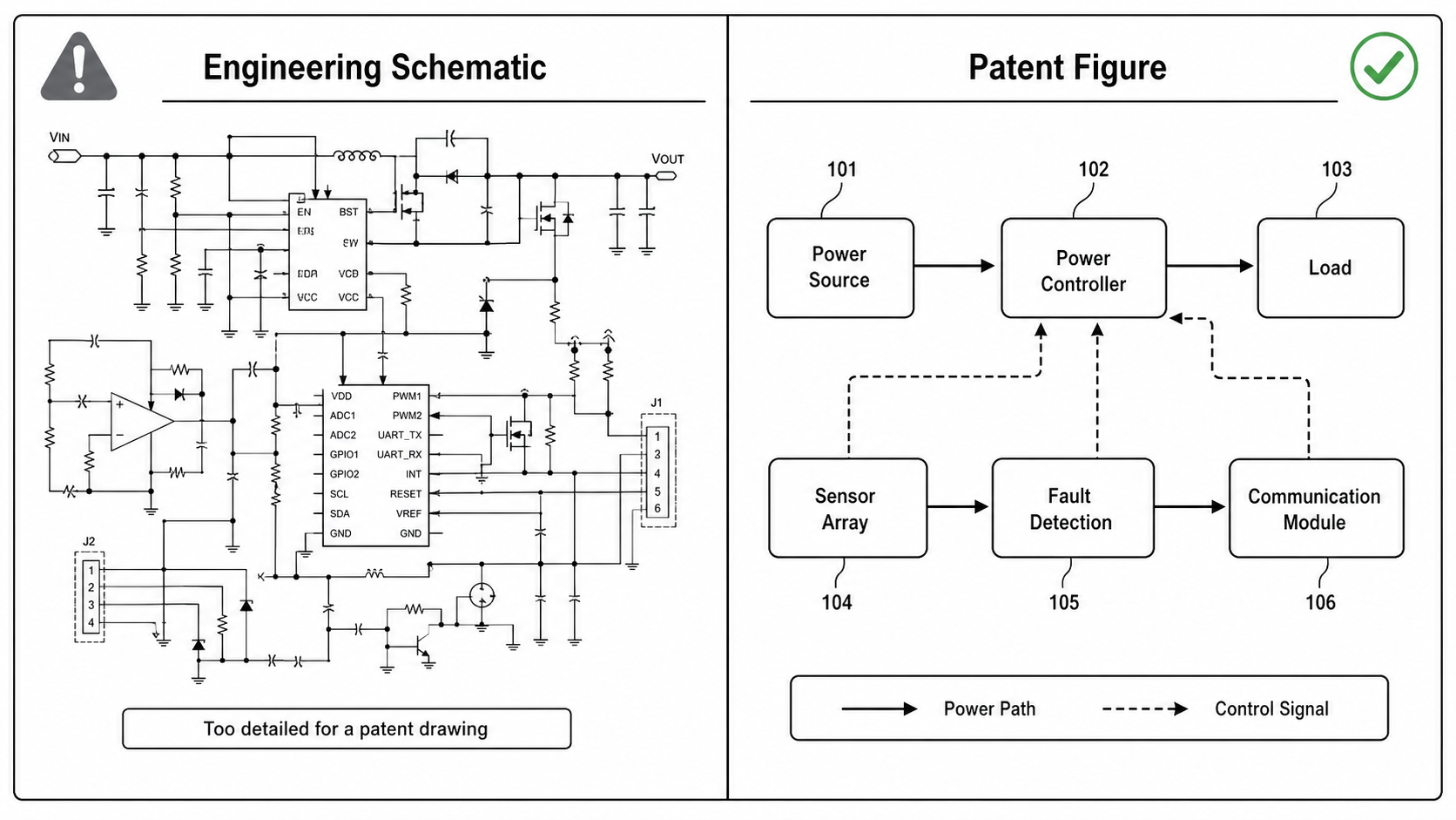
Patent Figures Explain Relationships
A patent drawing should make the claimed relationship easy to understand. For electrical inventions, that often means separating:
- power source
- distribution controller
- sensor array
- actuator or load
- communication module
- control signal path
- safety or fault-detection block
The figure does not need every component value, resistor tolerance, connector part number, or layout detail unless those details matter to the invention.
Engineering Schematics Verify Implementation
Engineering schematics have another job. They support manufacturing, simulation, debugging, safety review, and compliance testing. They contain details a patent figure may intentionally omit.
Do not promise that a generated patent diagram is a safe or buildable circuit. Treat it as a drafting layer for disclosure.
What To Remove From An Engineering Schematic
When converting an engineering source into a patent figure, remove details that do not support the disclosure:
- manufacturer part numbers
- resistor and capacitor values unless they are central to the invention
- test points, debug connectors, and layout notes
- dense net names that are not discussed in the specification
- board routing details better handled in engineering files
Then preserve the relationships that matter: source, controller, sensor, load, signal direction, fault handling, and feedback.
Practical Drawing Pattern
For many electrical filings, use three figures:
- A high-level system block diagram.
- A power or signal routing figure.
- A method flowchart for control logic.
If the invention is circuit-specific, add a simplified circuit patent drawing rather than pasting a dense EDA schematic.
What To Check Before Export
Before filing, verify that every numbered component appears in the specification, every arrow has a clear meaning, and the final export passes the Figure Checker.
Patent Figure vs Engineering Schematic
| Question | Patent figure | Engineering schematic |
|---|---|---|
| Primary reader | Examiner, attorney, technical reviewer | Electrical engineer, manufacturer, tester |
| Purpose | Explain invention relationships | Verify and build implementation |
| Detail level | Functional blocks and key paths | Component values, nets, tolerances, layout notes |
| Risk if copied directly | Too dense for disclosure | Not enough context for claims |
| Review needed | Patent support and drawing compliance | Electrical safety and engineering correctness |
Prompt Template For PatentFig AI
Create a patent-style electrical diagram from this engineering description.
Show the power source, controller, sensor array, load, communication module, and fault detection block.
Use reference numerals, arrows for power path and control signal, and black-and-white line art.
Do not include component values, dense net names, or PCB layout details unless they are part of the invention.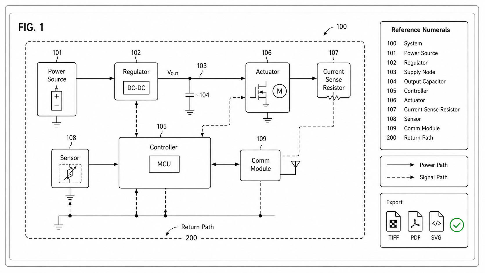
Export Checklist
| Check | What to verify |
|---|---|
| Power path | Source, distribution, storage, and load are visually traceable |
| Control path | Controller inputs and outputs are not confused with power arrows |
| Safety language | The figure does not imply electrical certification |
| Numerals | Each block can be mapped to written description terms |
| Related figures | Circuit-level details are separated when the system figure becomes crowded |
A Diagram That Stops at the Claim Boundary
For electrical inventions, the most useful test before export is whether the figure shows exactly what the broadest independent claim requires — no more. Test points, debug headers, sense-resistor values, and PCB routing all belong in the engineering schematic. A patent figure that includes them invites narrower reading of the claim than the disclosure intends. Strip back to the elements that support the claim language, and let the engineering file carry the rest.
Open the electrical patent diagram generator.
Next step: Browse 25 patent drawing examples by category — or open the generator and adapt the closest one to your invention.
Author

Categories
More Posts
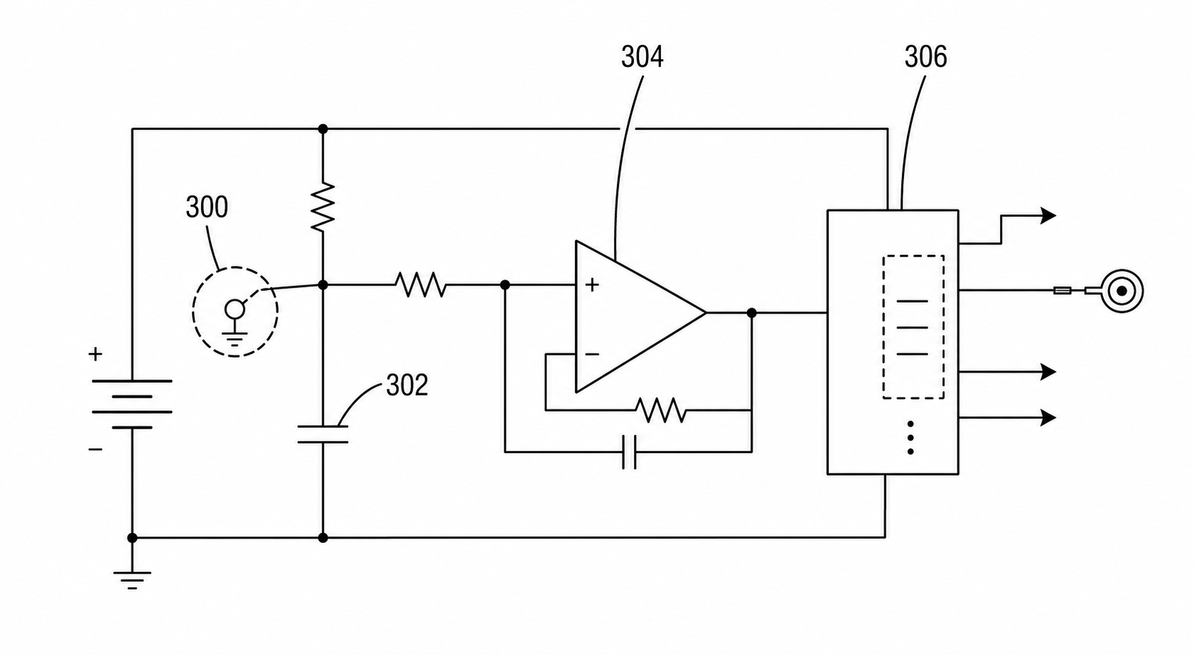
Circuit Patent Drawing Examples for Utility Patent Applications
Examples of circuit patent drawings for signal paths, sensor circuits, control loops, power routing, and functional blocks in utility patent filings.
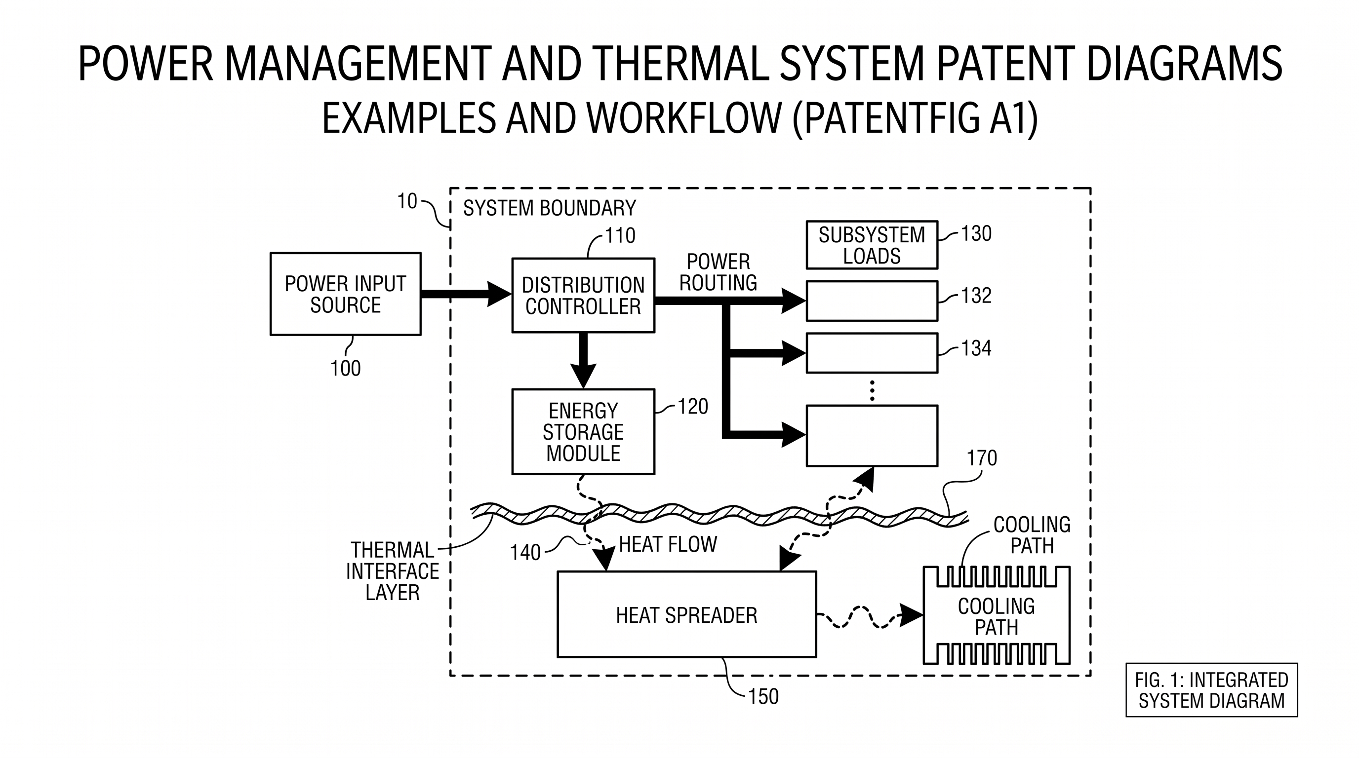
Power Management and Thermal System Patent Diagrams: Examples and Workflow
Create clearer patent diagrams for power routing, energy storage, thermal stacks, sensors, cooling paths, block diagrams, and cross-sections.
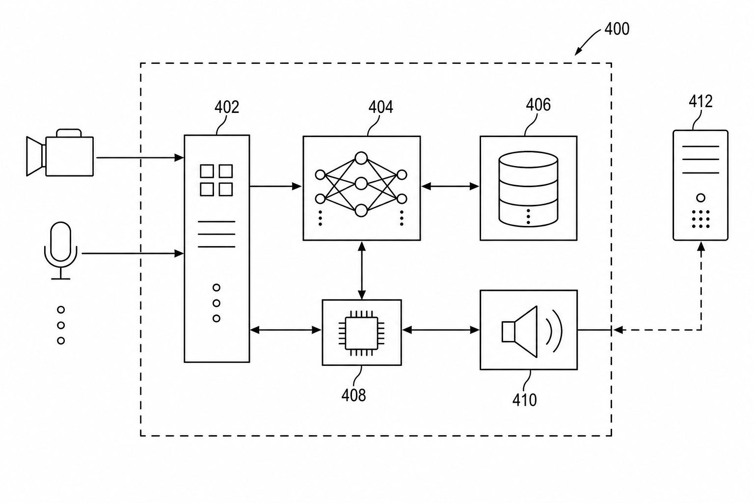
Patent Block Diagram Examples for Software, Hardware, and AI Systems
How to structure patent block diagrams for software systems, hardware products, AI workflows, networked devices, and platform inventions.
Newsletter
Join the community
Subscribe to our newsletter for the latest news and updates