Circuit Patent Drawing Examples for Utility Patent Applications
Examples of circuit patent drawings for signal paths, sensor circuits, control loops, power routing, and functional blocks in utility patent filings.
TL;DR: A circuit patent figure should sit between a vague block diagram and a full engineering schematic: show the functional signal path (sensor → conditioning → converter → controller → output) with reference numerals, and include component values only when they are the inventive feature. Keep the buildable schematic in the EDA file for the manufacturing team — the patent figure carries just the relationships the claims rely on, with control loops split into a circuit block diagram plus a method flowchart.
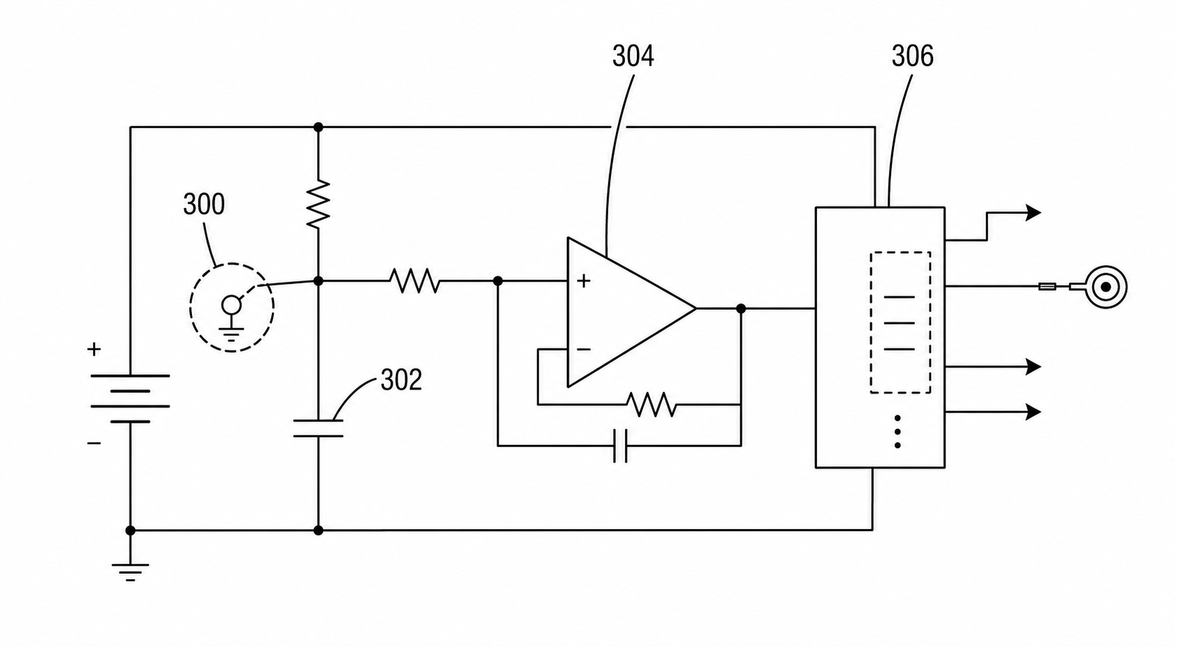
Circuit inventions can be underdrawn or overdrawn. A vague block diagram may fail to explain the signal path, while a full engineering schematic may bury the invention inside component noise.
The circuit patent drawing generator is for the middle layer: clear enough for patent disclosure, conservative enough for filing review.
Common Drafting Mistakes
Circuit figures become weak when they either hide the invention inside one vague block or copy a complete engineering schematic without context. A patent drawing should help the reader see the functional relationship that supports the claim.
Avoid these patterns:
- labeling one box "circuit" without showing the signal path
- including every resistor value when values are not the inventive feature
- mixing power routing, sensor conditioning, and software control in one crowded sheet
- using unlabeled arrows that do not distinguish power, data, control, or feedback
- omitting reference numerals that the written description needs later
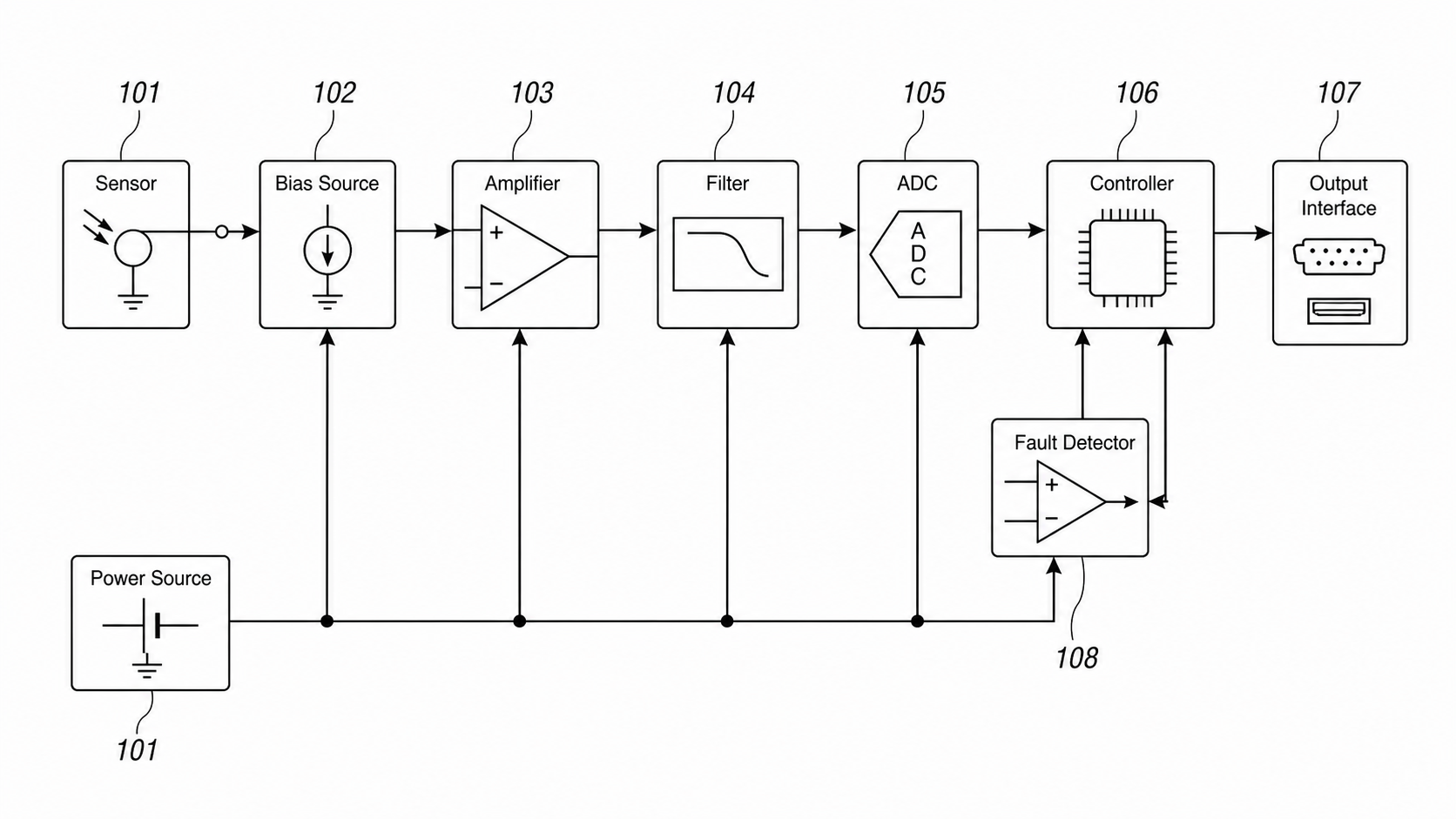
Example 1: Sensor Signal Conditioning
A sensor circuit figure may show:
- sensing element
- bias or excitation source
- amplifier
- filter
- analog-to-digital converter
- controller
- output interface
If the invention is about the arrangement of the signal path, show that arrangement directly. Do not force readers to decode a full schematic.
Example 2: Power Routing Circuit
Power inventions often need separate figures for:
- input source
- switch or regulator
- storage element
- load
- fault detector
- controller logic
This can link naturally to an electrical patent diagram when the invention is a system, not just a circuit.
Example 3: Control Loop
Control loops are often better as a hybrid figure: one circuit block diagram plus one method flowchart. The block diagram shows the physical relationship; the flowchart shows the ordered logic.
Drafting Rule
Use circuit detail only where the detail supports the claim. Everything else should be simplified into readable patent line art and checked before export.
Which Circuit Figure Should You Draw?
| Invention focus | Useful figure | What to emphasize |
|---|---|---|
| Sensor signal path | Functional signal path diagram | Sensor, conditioning, conversion, controller, output |
| Power routing | Power path figure | Source, switch, regulator, storage, load, fault detector |
| Control loop | Circuit block + method flowchart | Measurement, decision, actuation, feedback |
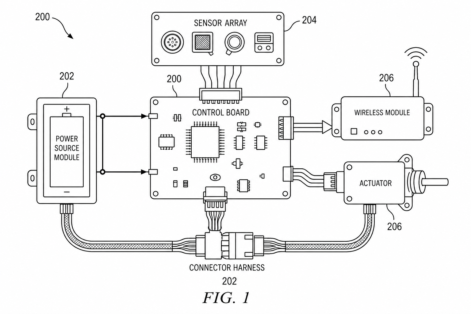
| Mixed hardware/software | System block diagram | Controller boundary, firmware logic, physical circuit interface |
| Component arrangement | Detail figure | Only the component relationships that matter to the claim |
Prompt Template For PatentFig AI
Create a patent-style circuit figure for a utility patent application.
Show a readable signal path from [sensor/input] through [conditioning block], [converter], [controller], and [output interface].
Include reference numerals, arrows for signal and power flow, and black-and-white line art.
Do not create a dense engineering schematic or include component values unless they are part of the invention.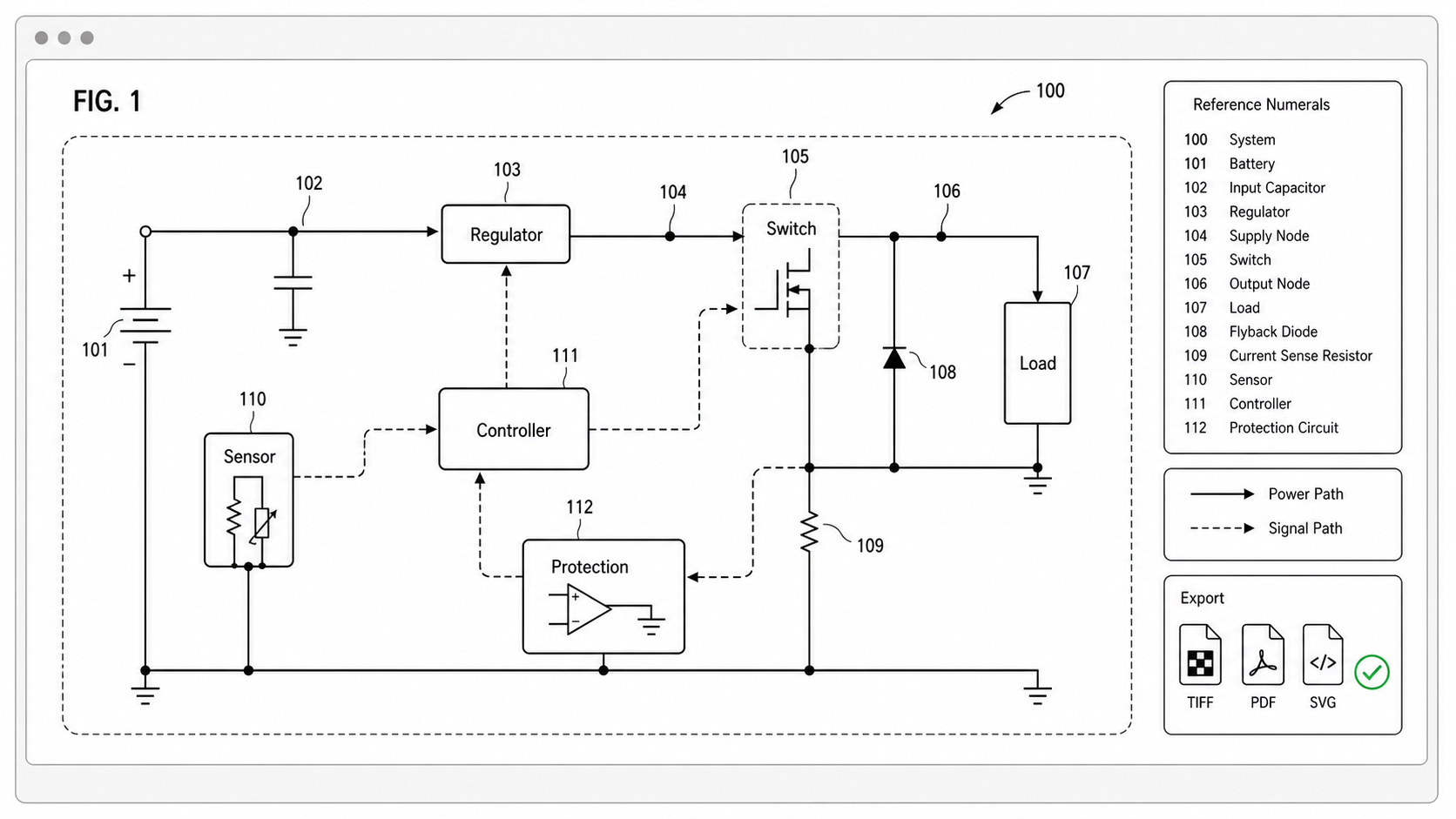
Before Export: Circuit Figure Checklist
| Check | Pass condition |
|---|---|
| Signal path | The claimed path can be followed without decoding a full schematic |
| Power path | Power source, regulator, load, and protection blocks are clear when relevant |
| Numerals | Each important element can be referenced in the specification |
| Labels | Blocks use technical names rather than marketing names |
| Separation | Circuit structure and control method are split when one sheet becomes crowded |
| Review | Engineering accuracy is reviewed separately from patent figure readability |
Splitting Engineering Accuracy From Patent Readability
The most common circuit-figure mistake is asking the patent diagram to also serve as a buildable engineering schematic. They have different readers and different rules. Keep the engineering schematic in the EDA file for the manufacturing team, and produce a separate patent figure that retains only the functional relationships the claims actually rely on. That separation also protects the disclosure: a figure shaped around the invention is harder to read as a public release of unrelated implementation detail.
Open the circuit patent drawing generator.
Next step: Browse 25 patent drawing examples by category — or open the generator and adapt the closest one to your invention.
Author

Categories
More Posts
Electrical Patent Drawings: Patent Figure vs Engineering Schematic
Electrical patent drawings should explain invention relationships, not replace engineering schematics. Learn how to draw power paths, sensors, control signals, and system blocks.
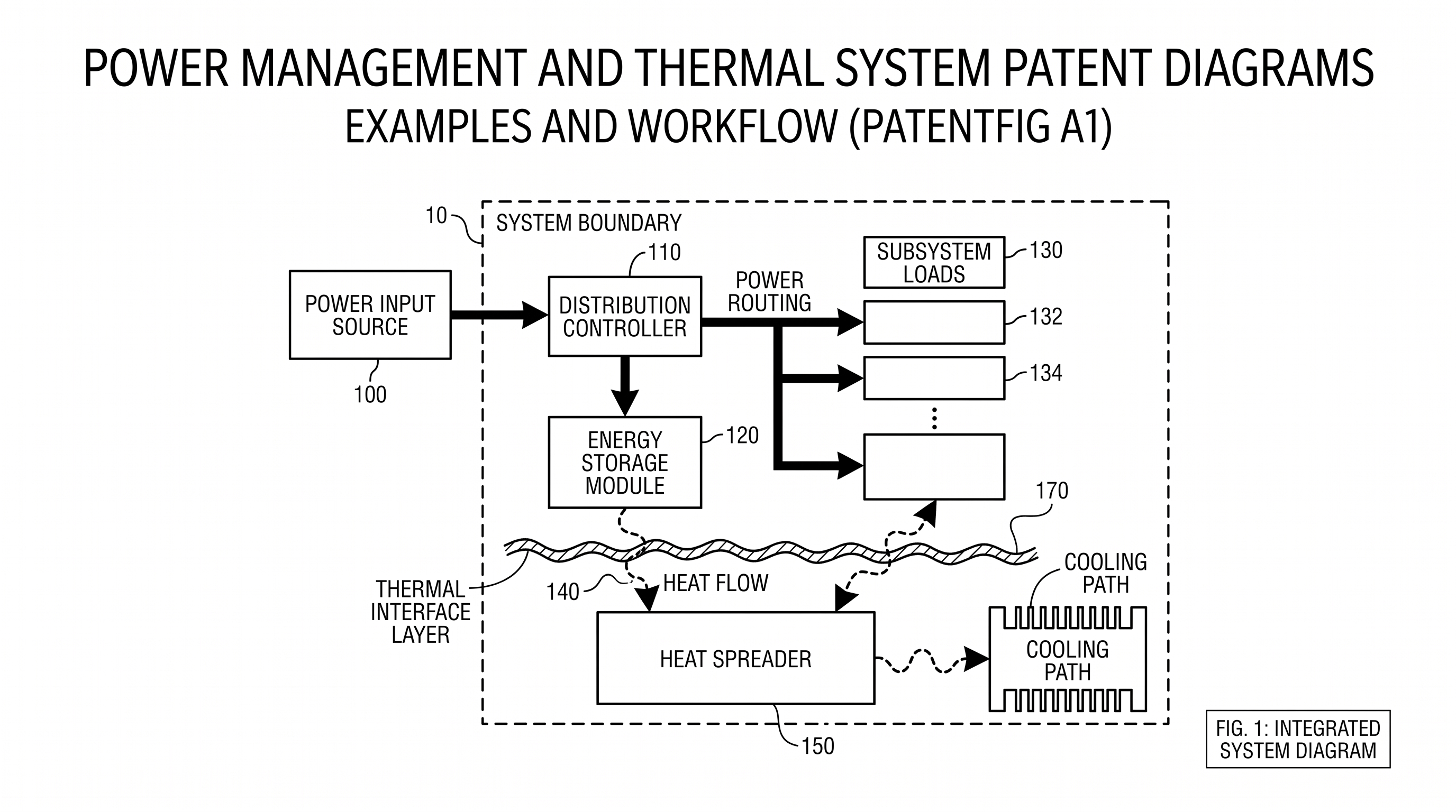
Power Management and Thermal System Patent Diagrams: Examples and Workflow
Create clearer patent diagrams for power routing, energy storage, thermal stacks, sensors, cooling paths, block diagrams, and cross-sections.
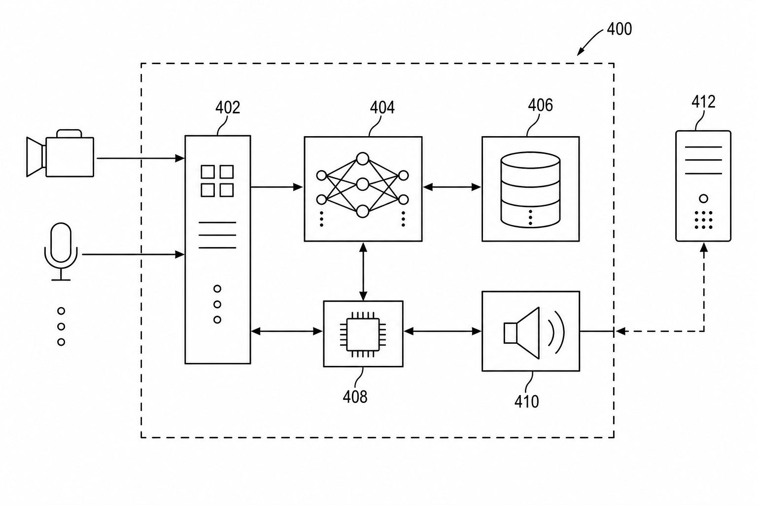
Patent Block Diagram Examples for Software, Hardware, and AI Systems
How to structure patent block diagrams for software systems, hardware products, AI workflows, networked devices, and platform inventions.
Newsletter
Join the community
Subscribe to our newsletter for the latest news and updates