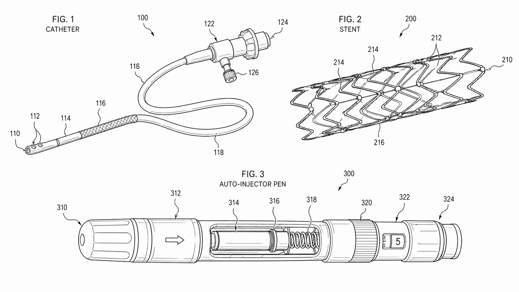
Medical Device Patent Drawing Checklist: Catheters, Stents, Implants, and Auto-Injectors
A practical medical device patent drawing checklist plus reusable prompt templates for use-states, cross-sections, and exploded auto-injector assemblies.
TL;DR: Medical device figures fail filing for predictable reasons — a stent that loses its reference numeral when it deploys, a catheter cross-section taken at an unlabeled cut plane, an auto-injector exploded view with parts that drift out of alignment. This is a working checklist plus copy-ready prompt templates for the four hardest figure types in this space: multi-state devices, layered cross-sections, exploded delivery systems, and use-states that show only the anatomy the claims actually need.
Catheters, stents, implants, and auto-injectors share a problem most mechanical inventions do not: the device changes shape during use. A stent is one geometry crimped on a balloon and another expanded in a vessel; an auto-injector hides its needle, deploys it, then locks a guard over it. The figure set has to capture those transformations while keeping every reference numeral pinned to the same physical part — all in black-and-white line art on a pure white background, with no clinical realism the claims do not require.
This post is the checklist. It complements our companion piece on medical device exploded views, cross-sections, and use states — that one covers which views to plan; this one gives you the pre-filing checks and reusable prompts to produce them.
The Governing Rule: Figures Show Only What Claims Need
Before any checklist item, internalize the one rule that catches the most rework: a patent figure depicts the invention, not the product. Under USPTO 37 CFR §1.84 (and the parallel rules at CNIPA, EPO, JPO, and KIPO), drawings must show every claimed feature — and they are not required, or even encouraged, to show more.
For medical devices this rule does double duty. Anatomy and clinical context are seductive: it is tempting to draw a realistic coronary artery, a textured tissue bed, a hand gripping the injector. Resist it. Show anatomy only to the extent needed to make device-to-body orientation legible, and render it schematically — a generic vessel wall as a pair of broken lines, a tissue plane as a simple boundary. Three reasons:
- Consistency. Photorealistic anatomy is nearly impossible to keep identical across deployed, retracted, and collapsed views. Schematic anatomy is.
- Scope. Detailed anatomy can be read as importing limitations the claims never intended.
- Classification. Heavy clinical realism makes a figure look like instructions-for-use (IFU) or marketing artwork, neither of which is a disclosure figure.
Keep patent figures in their own track, drawn against the specification rather than the regulatory submission.
Checklist 1: Use-States (Deployed / Retracted / Collapsed)
Multi-state devices are where reference-numeral discipline breaks down. Use this pass before you consider the state figures done.
Numeral consistency across states
- One numeral per physical part, reused in every state. A stent that is element
30crimped is element30expanded. Never renumber a part because its shape changed. - Suffix convention defined in the spec. If you show the same part in two positions, use
30and30'(prime) or30a/30b, and state the convention in the written description. - Numerals placed outside the part, with squiggly lead lines (freehand-style leaders) touching the surface they identify. Never write a numeral on top of hatching or a lumen.
- Every numeral that appears in any state also appears in the specification — and vice versa. This is the single most-cited drawing defect; multi-state sets multiply the chances of an orphaned numeral.
State coverage
- Each claimed configuration has its own figure (e.g., crimped/collapsed, partially deployed, fully expanded).
- A consistent viewing axis across states so the reader can track the transformation.
- Motion or expansion shown with the device's own geometry, not with arrows alone; reserve arrows for direction of actuation where the claim depends on it.
- Balloon, sheath, or delivery member shown in the states where it is claimed and omitted (or broken-line) where it is not part of the claimed subject matter.
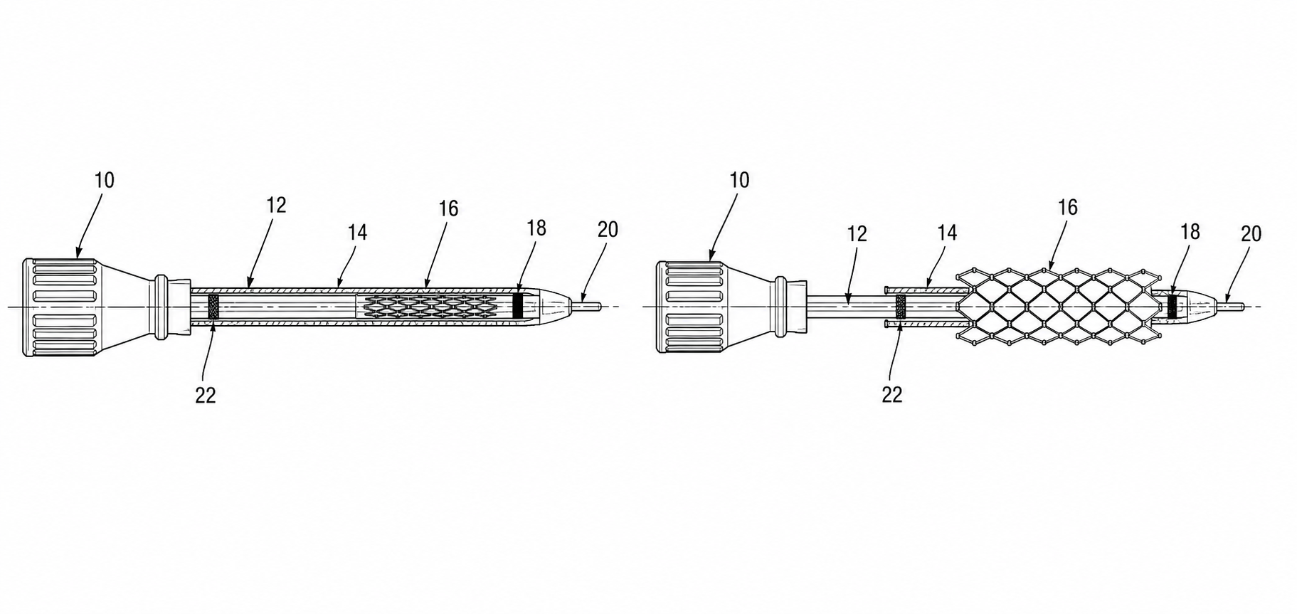
Prompt template — use-states
Create a black-and-white patent line drawing set on a pure white background.
Subject: [device, e.g. self-expanding stent on a delivery catheter].
Show [N] use-states as separate figures on a consistent viewing axis:
  FIG. 1 — collapsed/crimped within the delivery sheath
  FIG. 2 — partially deployed (sheath retracted)
  FIG. 3 — fully deployed / expanded
Reuse one reference numeral per physical part across ALL figures:
  stent body = 30, struts = 32, delivery sheath = 40, guidewire lumen = 42.
Numerals placed outside the parts with squiggly lead lines; no numeral over hatching.
Show only the anatomy needed for orientation: a generic vessel wall as two broken lines.
No color, no shading beyond light section hatching, no clinical realism, no patient detail.
Checklist 2: Cross-Sections of Catheters, Stents, and Implants
Cross-sections carry the internal-structure claims — lumens, layers, seals, drug reservoirs, strut profiles. They are also where examiners look hardest for support.
Cut planes and section discipline
- Every transverse section references a labeled cut plane on a parent figure: "FIG. 4 is a section taken along line 4-4 of FIG. 2." The cut line and arrows appear on the parent figure.
- A transverse section at every point where internal geometry changes — where a single lumen splits into a working lumen plus an inflation lumen, where wall construction transitions, where a reservoir begins.
- A longitudinal section through the working length for catheters and implants whose claim depends on axial layering (e.g., a tip transition, an eluting coating, an anchoring feature).
Hatching and layer legibility
- Hatching distinguishes materials, not decoration: different angles or spacing for a braided reinforcement layer vs. a polymer jacket vs. a lumen wall. Keep it light so numerals stay readable.
- Adjacent different parts use different hatching directions so the boundary reads at a glance.
- Lumens and voids left white, clearly bounded — never hatched.
- Coatings, drug layers, and thin films shown with their own line type and labeled; do not let a thin layer collapse into the contour line beside it.
- No color used to separate layers — line type and hatching only, per USPTO 37 CFR §1.84 and CNIPA practice.
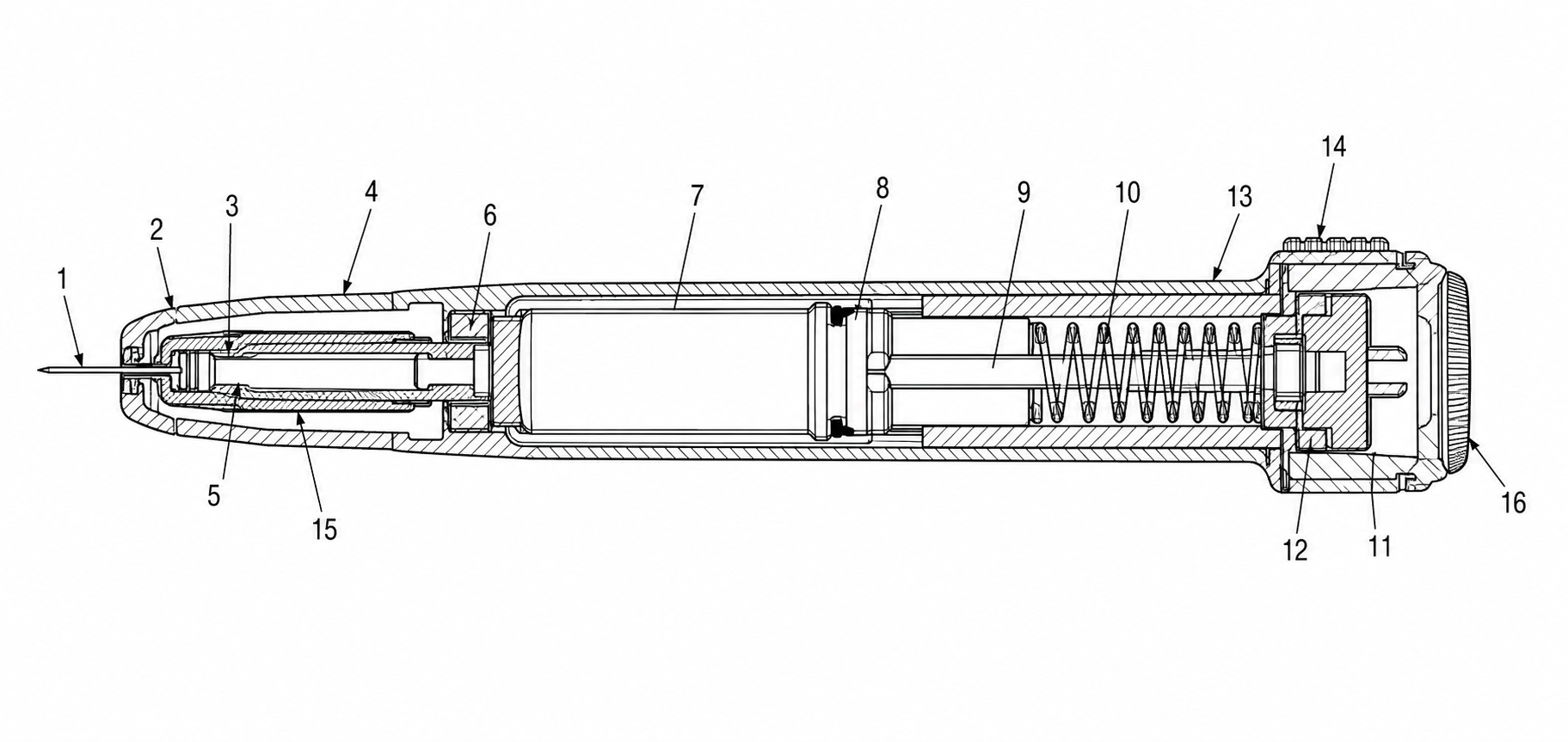
Prompt template — cross-section
Create a black-and-white patent cross-section line drawing on a pure white background.
Subject: transverse section of a [multi-lumen catheter shaft].
Show the section taken along a labeled cut plane (line 4-4 of the parent figure).
Distinguish layers with different hatching angles, kept light:
  outer jacket = 50, braid reinforcement layer = 52, working lumen = 54 (left white),
  inflation lumen = 56 (left white), inner liner = 58.
Lumens and voids remain white and clearly bounded; no hatching inside lumens.
Reference numerals outside the parts on squiggly lead lines.
No color, no gray fills, no clinical realism. Pure line art only.
Checklist 3: Exploded Assemblies of Auto-Injectors
Auto-injectors are assemblies first and mechanisms second. The exploded view earns its place when the claim turns on how parts stack and engage: the drive spring, plunger, cartridge or syringe, activation collar, needle guard, and cap.
Alignment and assembly logic
- Parts arranged along a single explosion axis in assembly order, so the stack reads from cap to base without crossing leaders.
- Alignment / projection lines (light dashed or dot-dash leaders) connecting each part to its seated position, where they aid clarity — and not so many that they clutter the figure.
- Spacing proportional and consistent; a part should sit where it obviously belongs in the stack.
- Section or detail callout for any sub-mechanism the claim depends on — the rotational safety latch, the audible-click dose-end feature — rather than burying it in the exploded stack.
Part identity
- Same numerals as the assembled and cross-section figures. The drive spring is the same numeral exploded, sectioned, and assembled.
- Springs and elastomeric seals shown with conventional symbolic line work, labeled, not rendered photorealistically.
- Cartridge fill / drug reservoir left white and unlabeled as to contents unless the formulation is itself claimed.
Prompt template — exploded auto-injector
Create a black-and-white patent exploded-view line drawing on a pure white background.
Subject: [spring-driven auto-injector pen].
Arrange parts along a single vertical explosion axis in assembly order, cap to base:
  cap = 10, needle guard = 12, housing = 14, drive spring = 16, plunger rod = 18,
  cartridge/syringe = 20, activation collar = 22, base = 24.
Use light dashed alignment lines connecting each part to its seated position.
Keep numerals outside parts on squiggly lead lines; reuse the same numerals
that appear in the assembled and cross-section figures.
Spring drawn with conventional symbolic line work, not a photoreal coil.
No color, no shading, no clinical realism. Clean, evenly spaced exploded stack.
Checklist 4: The Cross-Cutting Compliance Pass
Run these against the whole set, in every state and section, right before export.
| Check | What to verify | Common rule cited |
|---|---|---|
| Line weight | Contour lines survive a 300 DPI scan; leaders thinner but solid | USPTO 37 CFR §1.84(l) |
| Color mode | Bilevel black-and-white; no gray fills, no color | USPTO 37 CFR §1.84(a); CNIPA / EPO / PCT parallels |
| Numeral height | At or above the office minimum; legible at 100% print | USPTO 37 CFR §1.84(p) |
| Numeral consistency | Every numeral matches across states, sections, and the spec | most-cited drawing defect |
| Lead lines | Squiggly leaders touch their part; numerals placed outside the part | USPTO 37 CFR §1.84(q) |
| Cut planes | Each section references a labeled line on its parent figure | section-view practice |
| Anatomy scope | Only the orientation anatomy the claims need; schematic, not clinical | claim-support principle |
| Margins & sheet | Within margins; figure numbers and orientation correct | USPTO 37 CFR §1.84(c)–(d) |
Putting It Together: A Sample Auto-Injector Figure Set
A claim-driven set for a spring-driven auto-injector typically lands at:
- FIG. 1 — overall external view (orientation, overall form).
- FIG. 2 — exploded assembly (spring–plunger–cartridge–guard stack).
- FIG. 3 — longitudinal cross-section (internal seating, fluid path).
- FIG. 4 — transverse section at a labeled cut plane (cartridge / drive interface).
- FIGS. 5–8 — use-states: pre-activation, needle deployed, dose complete, guard locked.
- FIG. 9 — detail view of the claimed safety latch.
Every part keeps its numeral from FIG. 2 through FIG. 9. That single rule — one numeral per part, everywhere — is what separates a set that sails through formalities from one that comes back with an objection.
How PatentFig AI Helps
PatentFig AI generates the entire set above as office-compliant black-and-white line art from a description, sketch, photo, or 3D model — multi-view and multi-state sets with reference numerals carried consistently across deployed, retracted, and collapsed figures. Use chat-to-modify editing to refine a cut plane or relabel a part without redrawing, regenerate a single slot when one figure needs work, and run the Figure Checker to catch the orphaned-numeral and line-weight defects that derail multi-state medical filings. Convert, enhance to 600 DPI, and vectorize to SVG or DXF when you are ready to file.
Start from the medical device patent drawing generator, drop in one of the prompt templates above, and adapt it to your claim set.
Next step: Browse the patent drawing examples by category to see compliant catheter, stent, and auto-injector figures — then open the medical device patent drawing generator and build your set.
Author

Categories
More Posts
Automotive Patent Drawings: Powertrain, EV Battery Packs, ADAS, and Wiring Harnesses
A practical guide to automotive patent drawings: which figure type supports which claim across powertrain, EV battery packs, ADAS, and wiring harnesses.
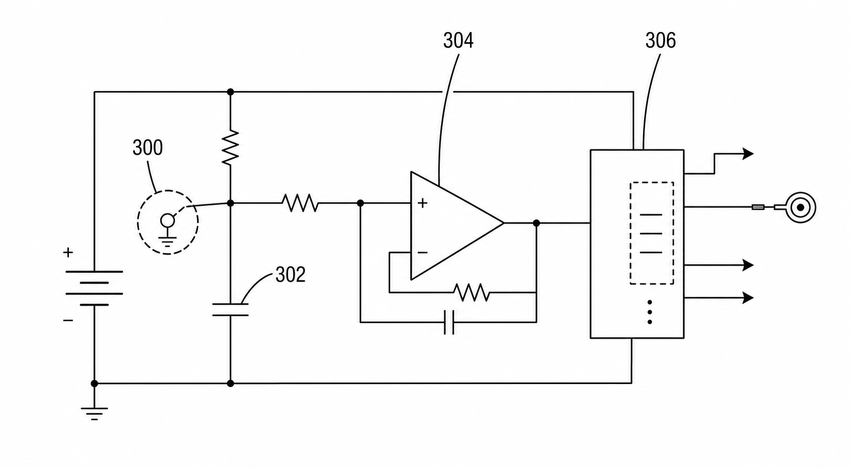
Circuit Patent Drawing Examples for Utility Patent Applications
Examples of circuit patent drawings for signal paths, sensor circuits, control loops, power routing, and functional blocks in utility patent filings.
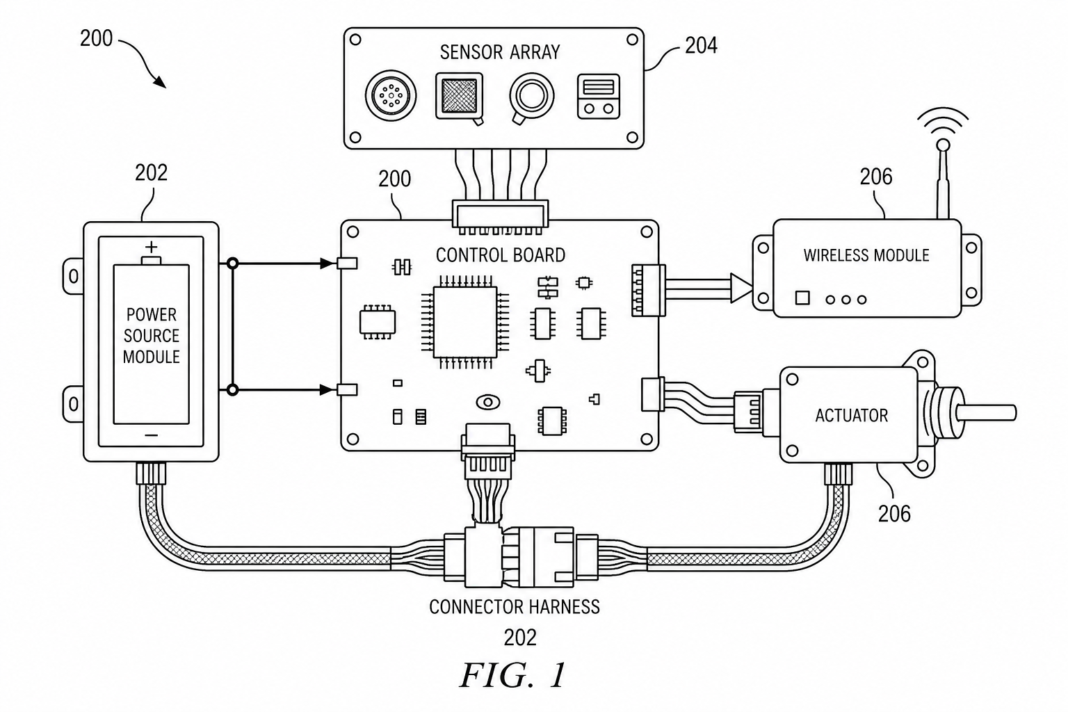
Electrical Patent Drawings: Patent Figure vs Engineering Schematic
Electrical patent drawings should explain invention relationships, not replace engineering schematics. Learn how to draw power paths, sensors, control signals, and system blocks.
Newsletter
Join the community
Subscribe to our newsletter for the latest news and updates