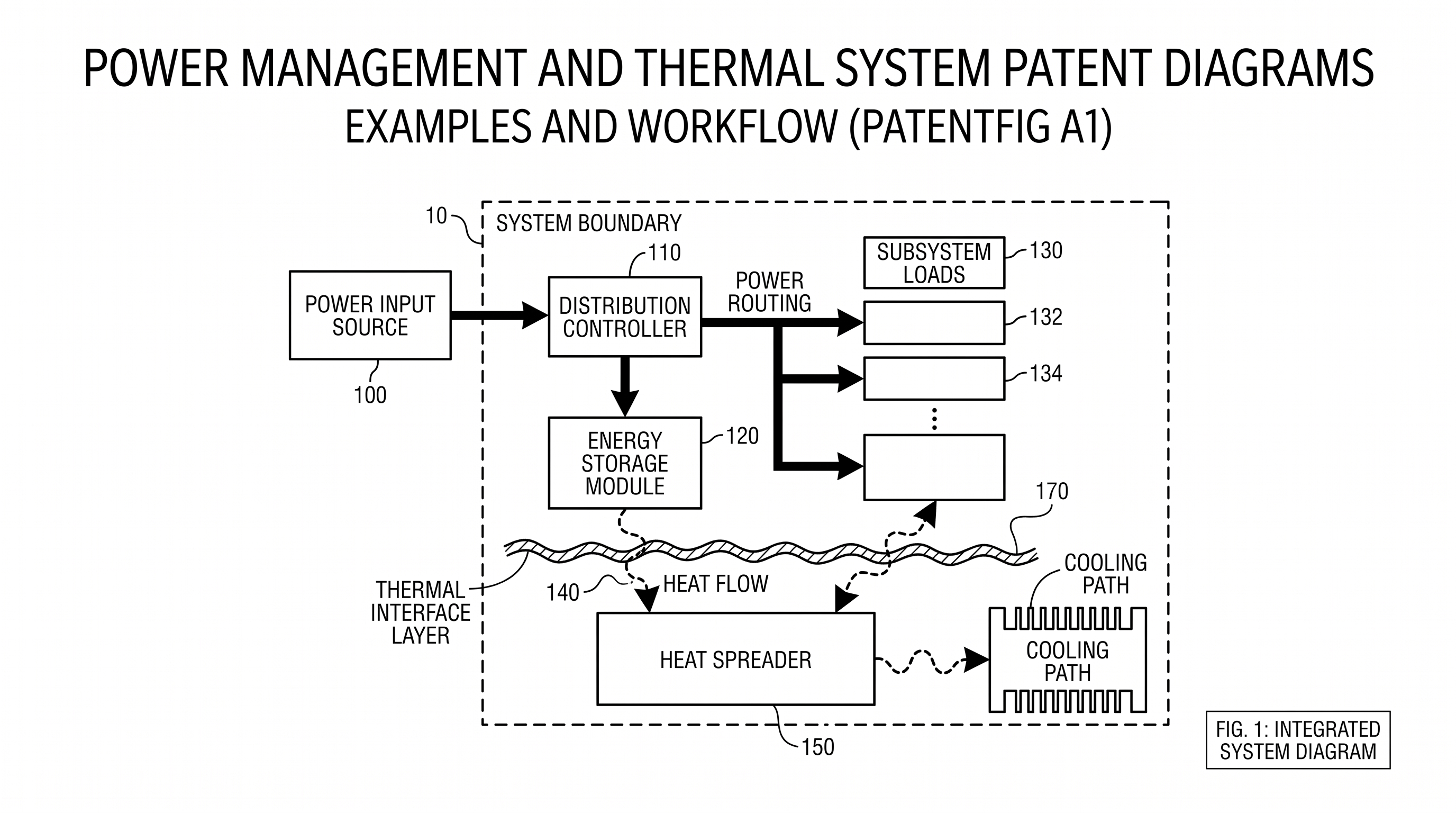
Power Management and Thermal System Patent Diagrams: Examples and Workflow
Create clearer patent diagrams for power routing, energy storage, thermal stacks, sensors, cooling paths, block diagrams, and cross-sections.
TL;DR: Split power-management and thermal inventions into a figure set — system overview, power routing diagram, control logic flow, energy storage detail, and a thermal stack cross-section — instead of one overloaded figure. Give each relationship its own line convention (solid arrows for power, dashed for control signals, open or paired arrows for heat; never color), and lock a reference numeral table before drawing so the same sensor does not change numbers between figures.
Power and thermal inventions are easy to overdraw. A single diagram may try to show an input source, distribution controller, battery, sensors, heat spreader, cooling path, load modules, firmware logic, and fault handling. The result looks technical, but the reader cannot tell which arrows carry power, which arrows carry control signals, and which arrows represent heat.
Need clearer system figures for power or thermal inventions? Try PatentFig AI in the generator.
The best figure set separates three questions:
- Where does power go?
- What decides how power is routed?
- Where does heat go?
For drawings prepared for patent submission, check the formal rules in the target jurisdiction. USPTO drawing practice is addressed in MPEP 608.02 and 37 CFR 1.84, while international teams often use PCT Rule 11 as a conservative baseline for reproducible line drawings.
This guide focuses on diagram design for power routing and thermal management, not on legal sufficiency.
Use A Figure Set, Not One Overloaded Figure
Power systems and thermal systems usually need multiple views because they mix physical components and functional logic.
A practical set may include:
- FIG. 1: high-level system architecture.
- FIG. 2: power routing block diagram.
- FIG. 3: controller logic or decision flow.
- FIG. 4: energy storage module detail.
- FIG. 5: thermal stack cross-section.
- FIG. 6: fault handling or throttling method.
If every arrow appears in FIG. 1, the figure becomes a wiring poster rather than a patent diagram. Use the overview to orient the reader, then use specific figures to explain the invention.
Separate Power, Control, And Heat
Use different visual conventions consistently.
| Relationship | Suggested line style | Example |
|---|---|---|
| Power path | Solid arrow | input source to controller to loads |
| Control signal | Dashed arrow | controller to switch or sensor feedback |
| Thermal path | Open arrow or paired arrows | battery to heat spreader to cooling channel |
| Mechanical stack | Sectioned layers | housing, pad, cell, bracket |
| Fault path | Labeled branch | over-temperature, under-voltage, disconnect |
Do not rely on color because patent figures often need to reproduce in black and white. If the figure uses line styles, define them visually and keep the number of styles small.
Patent Figure vs Engineering Schematic
An electrical patent figure is not a safety-approved schematic. It should explain the relationship between claimed components: power input, controller, sensor, storage, load, communication module, and fault path. Engineering schematics still belong in design review, simulation, and certification workflows.
If the invention is electrical at the system level, use the electrical patent diagram generator. If the invention turns on signal conditioning, circuit blocks, or a control loop, use the circuit patent drawing generator. For broader module relationships, start with the patent block diagram generator.
Example: Power Routing Block Diagram
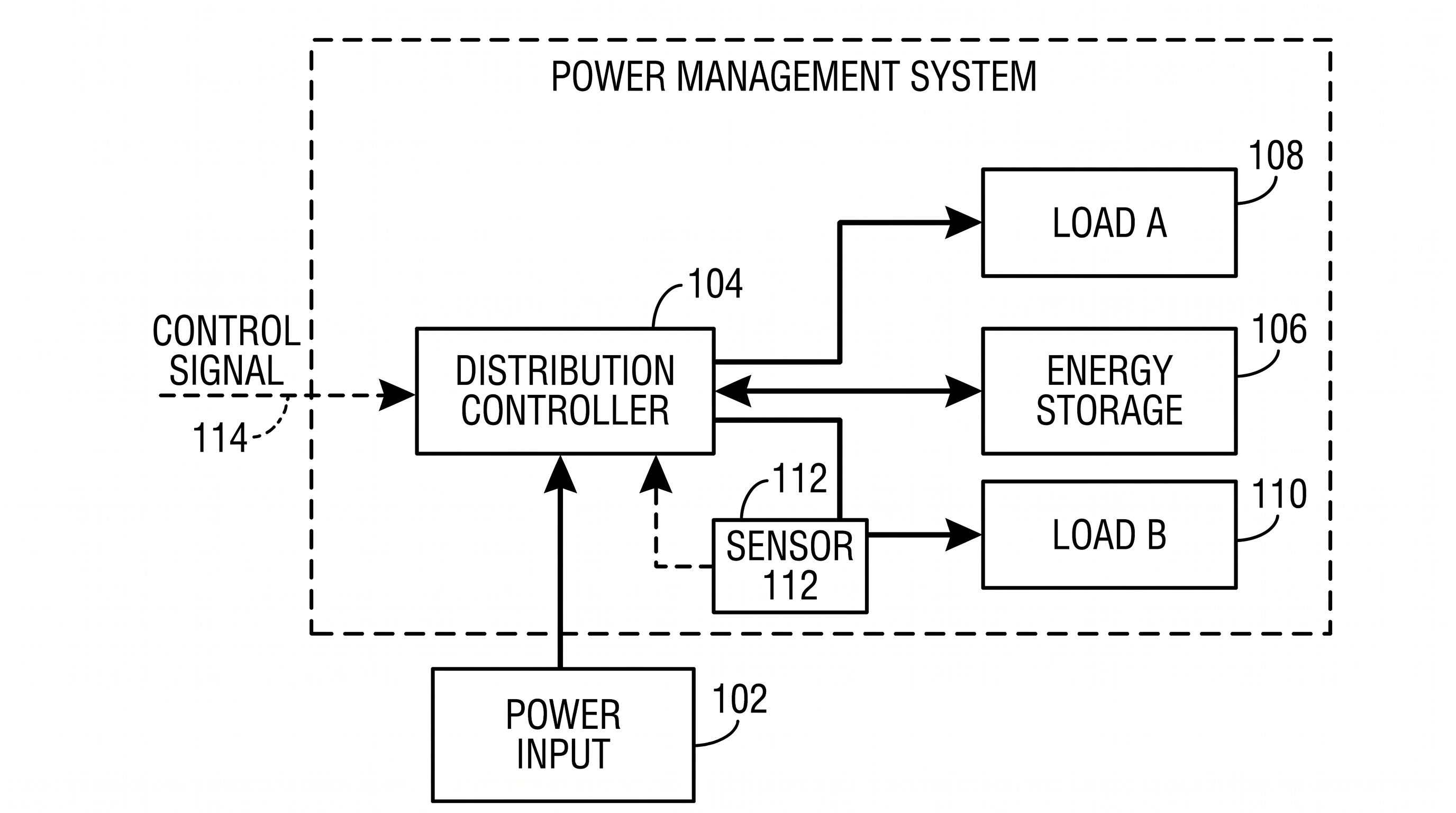
A power routing diagram should make direction and decision points obvious. It usually needs:
- Power input source.
- Power distribution controller.
- Energy storage module.
- One or more subsystem loads.
- Switching or routing elements.
- Sensor feedback.
- Control signal path.
- Fault or isolation branch if relevant.
For drafting, give each block a short noun phrase. Avoid full sentences inside the boxes. Use reference numerals near the boxes and leader lines only where needed.
Prompt example:
Create a black-and-white patent-style system block diagram for a power management system. Inside a dashed boundary labeled Power Management System, show Power Input Source 102, Power Distribution Controller 104, Energy Storage Module 106, Load Module A 108, Load Module B 110, Sensor 112, and Control Signal 114. Use solid arrows for power paths and dashed arrows for control signals. Keep all labels short and readable. Do not use color, gradients, or decorative icons.Example: Thermal Stack Cross-Section
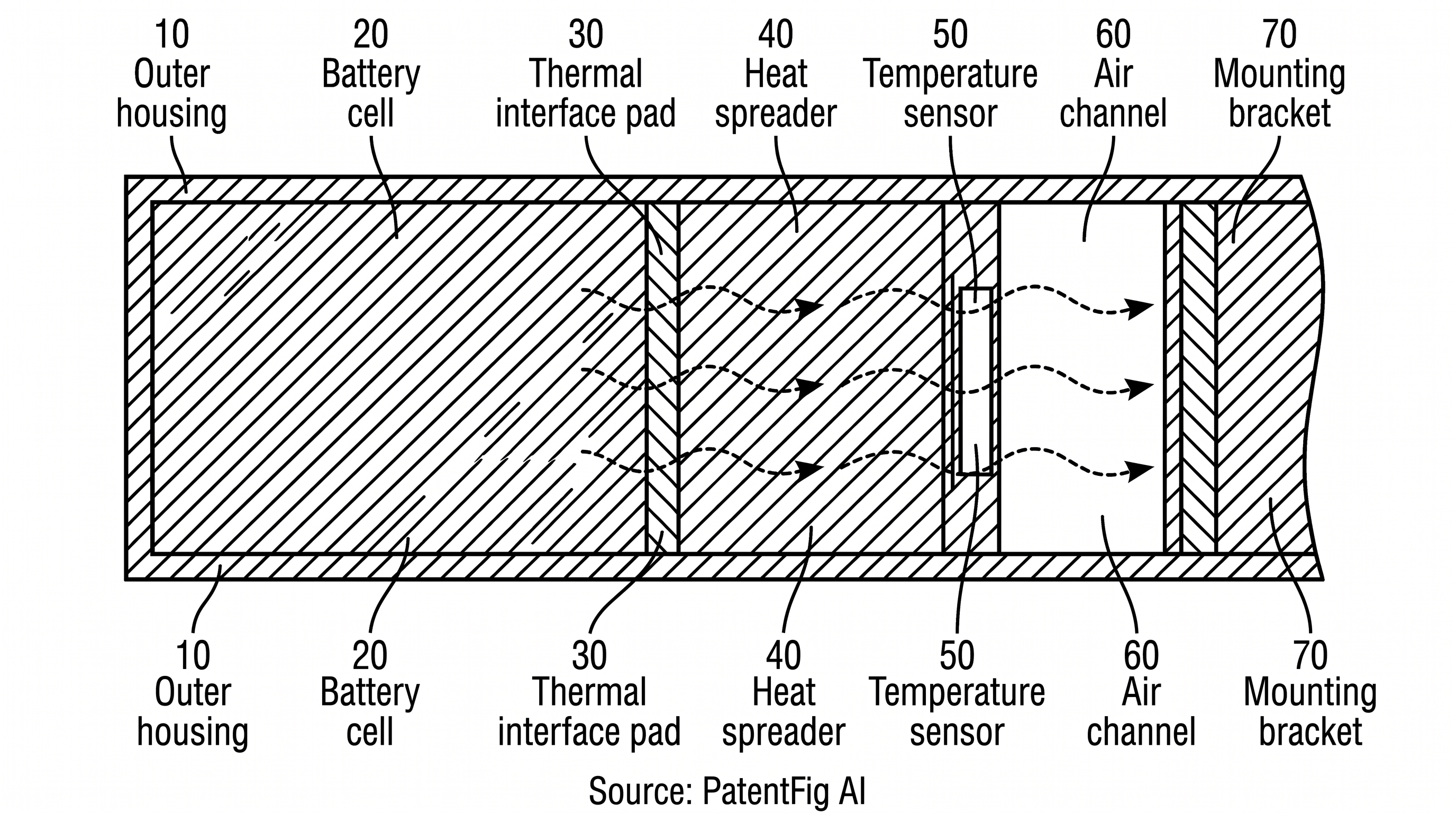
Thermal management is often physical. A block diagram cannot show layer contact, thickness relationship, air channel geometry, or sensor placement. Use a cross-section when the invention depends on:
- A thermal interface pad between a heat source and heat spreader.
- A battery cell pressed against a cooling plate.
- A sensor positioned near a hot zone.
- An air channel or liquid channel relative to a housing.
- A bracket, gap, fin, or contact surface.
- A layered material stack.
In a thermal cross-section, hatching helps, but too much hatching makes the diagram unreadable. Keep hatching minimal and avoid placing numerals on top of dense hatching.
Reference Numeral Strategy
Power and thermal diagrams often fail because the same thing gets renamed across figures.
Create a reference table before drawing:
| Component | Numeral range |
|---|---|
| System boundary | 100 |
| Power input and routing | 102 to 118 |
| Controller and logic | 120 to 138 |
| Energy storage | 140 to 158 |
| Thermal management | 160 to 178 |
| Sensors | 180 to 198 |
| Fault handling | 200 to 218 |
The ranges are not mandatory. The principle is what matters: keep the same component identity across diagrams. If “temperature sensor” is 180 in the thermal stack, do not call it 112 in the controller diagram unless the specification intentionally distinguishes two sensors.
Common Mistakes
- Every path in one figure. Split electrical routing, control logic, and thermal transfer.
- Unlabeled arrow meaning. Readers should know whether an arrow carries power, heat, data, or a command.
- Box labels too long. Patent diagrams should not contain paragraphs inside blocks.
- No physical view. Thermal inventions often need a cross-section, not only a block diagram.
- No controller context. Power routing usually needs the rule or decision point that changes routing.
- Color-dependent meaning. Use line style or labels instead of color alone.
Prompt Template For Power And Thermal Diagrams
Create a black-and-white patent-style diagram for [system name]. Figure type: [system block diagram / power routing diagram / thermal cross-section / control flowchart]. Show only these components: [component list]. Use reference numerals from [numbering plan]. Use solid arrows for power, dashed arrows for control, and labeled heat-flow arrows for thermal transfer. Keep labels short. Do not use color, gradients, decorative icons, logos, or unsupported components.For a revision:
Keep the current block layout unchanged. Change the arrow from Energy Storage 106 to Distribution Controller 104 into a bidirectional power path. Add Temperature Sensor 180 near the thermal interface pad. Do not add new load modules.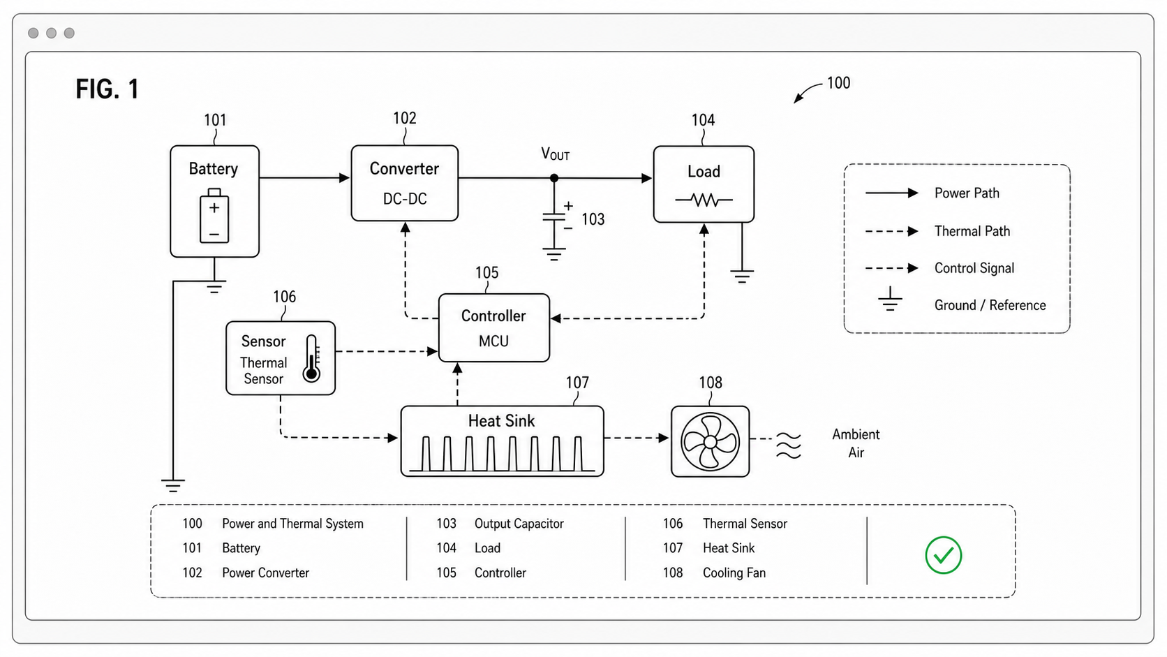
That level of specificity is what makes chat-based revision useful. It narrows the change without destabilizing the whole diagram.
A Practical Workflow
- Write a component list.
- Decide whether the invention is electrical routing, thermal transfer, control logic, or a combination.
- Create one high-level architecture diagram.
- Create separate detail figures for power paths and thermal layers.
- Assign reference numerals before final polish.
- Review arrow meanings and line styles.
- Export after checking readability in black and white.
PatentFig AI can generate the first figure set from a text prompt, then help revise specific arrows, labels, or component placement without redrawing everything.
Create Power And Thermal Patent Diagrams Faster
Ready to turn power routing notes, battery architecture, or thermal stack descriptions into clear patent figures? Open the PatentFig AI generator.
Next step: Browse 25 patent drawing examples by category — or open the generator and adapt the closest one to your invention.
Author

Categories
More Posts
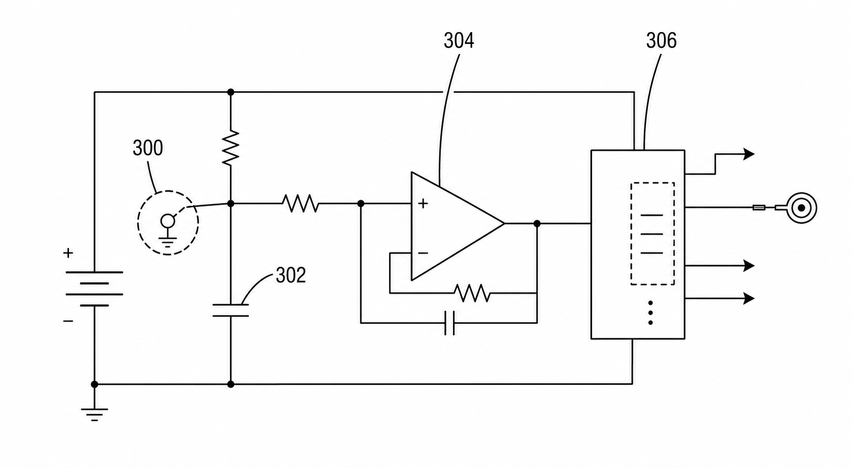
Circuit Patent Drawing Examples for Utility Patent Applications
Examples of circuit patent drawings for signal paths, sensor circuits, control loops, power routing, and functional blocks in utility patent filings.
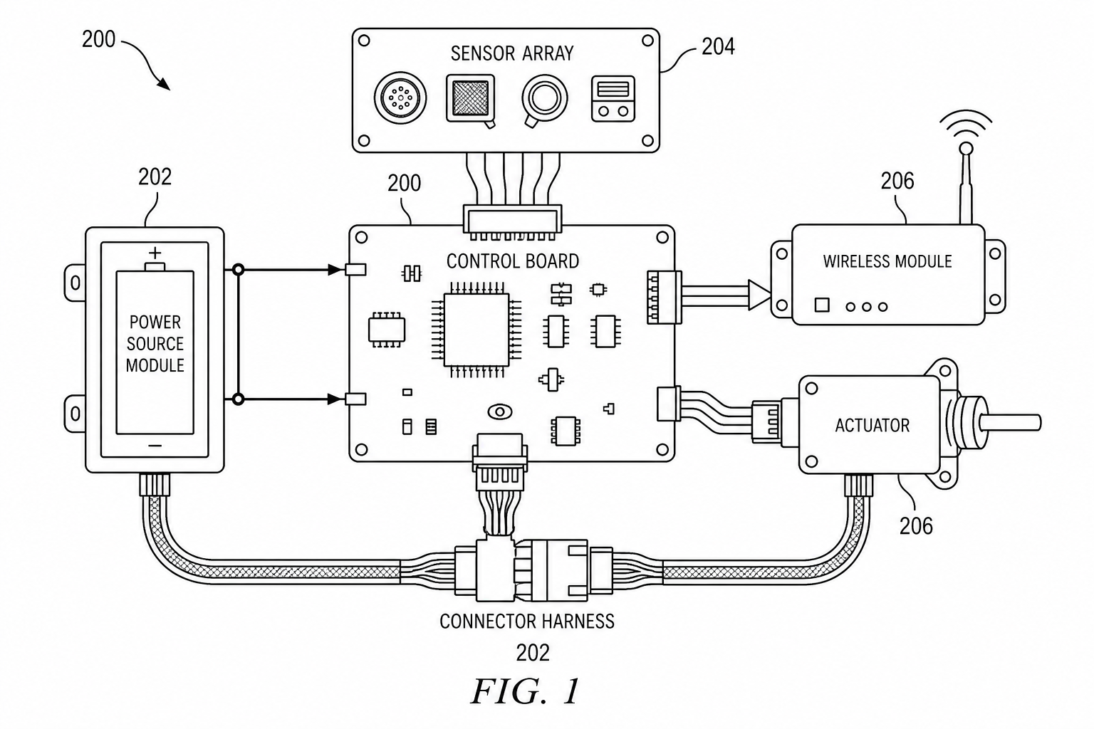
Electrical Patent Drawings: Patent Figure vs Engineering Schematic
Electrical patent drawings should explain invention relationships, not replace engineering schematics. Learn how to draw power paths, sensors, control signals, and system blocks.
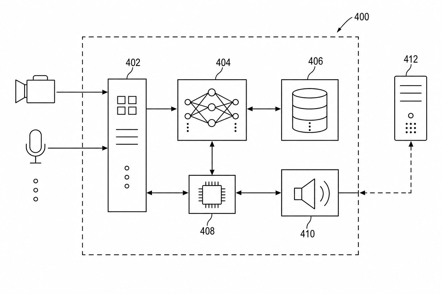
Patent Block Diagram Examples for Software, Hardware, and AI Systems
How to structure patent block diagrams for software systems, hardware products, AI workflows, networked devices, and platform inventions.
Newsletter
Join the community
Subscribe to our newsletter for the latest news and updates