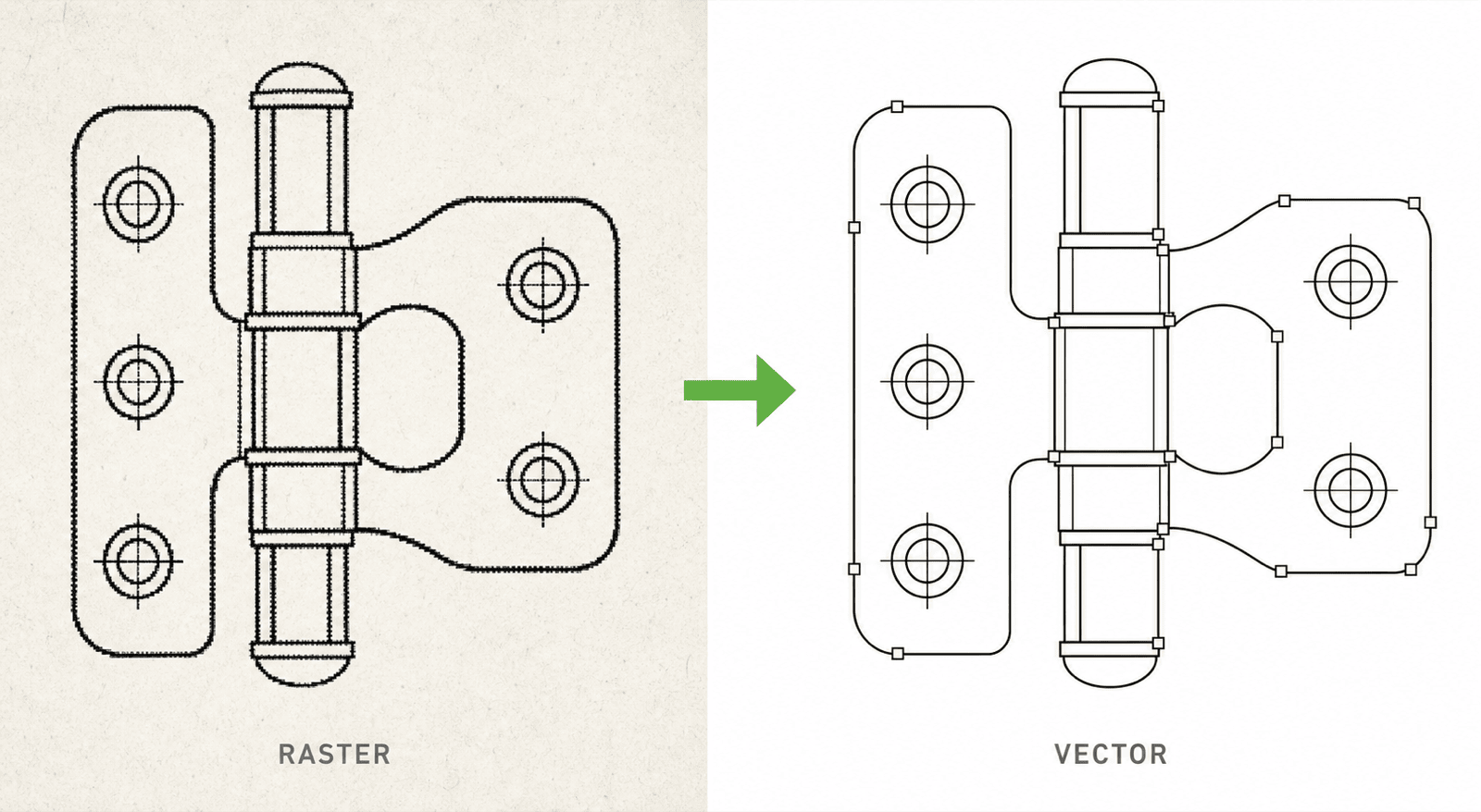
How to Vectorize Patent Drawings: Raster to Editable SVG/DXF Without Double Outlines
Why generic auto-tracing turns every patent line into two outlines, when centerline vectorization is the right tool, and a workflow for converting scans and PNG line art into editable SVG or DXF masters.
TL;DR: Generic auto-tracing converts every line of a patent drawing into two parallel outlines around a filled band — technically vector, practically uneditable. Patent line art needs centerline vectorization: one stroke path per drawn line. Feed it scans, PNG line art, or old patent figures (not photos), keep the resulting SVG/DXF as your editable master, and export TIFF or PDF only at filing time.
A scanned patent figure or a flattened PNG line drawing is frozen. You cannot change a line weight, move a reference numeral, or fix a hidden line without repainting pixels. Vectorization is how a frozen drawing becomes an editable one again — but only if the tracing method matches how patent drawings are actually constructed: as strokes, not as filled shapes.
Convert raster patent figures into editable vector paths with Vectorize — centerline output in SVG, DXF, or vector PDF.
Why generic auto-tracing produces double outlines
Most auto-trace features — including the ones built into general-purpose design tools — treat the input as a picture of regions: they find every dark area and wrap a contour around it. A drawn line is a long, thin dark region, so the tracer wraps a contour around both sides of it. The output for a single pencil-width line is two parallel paths enclosing a filled sliver.
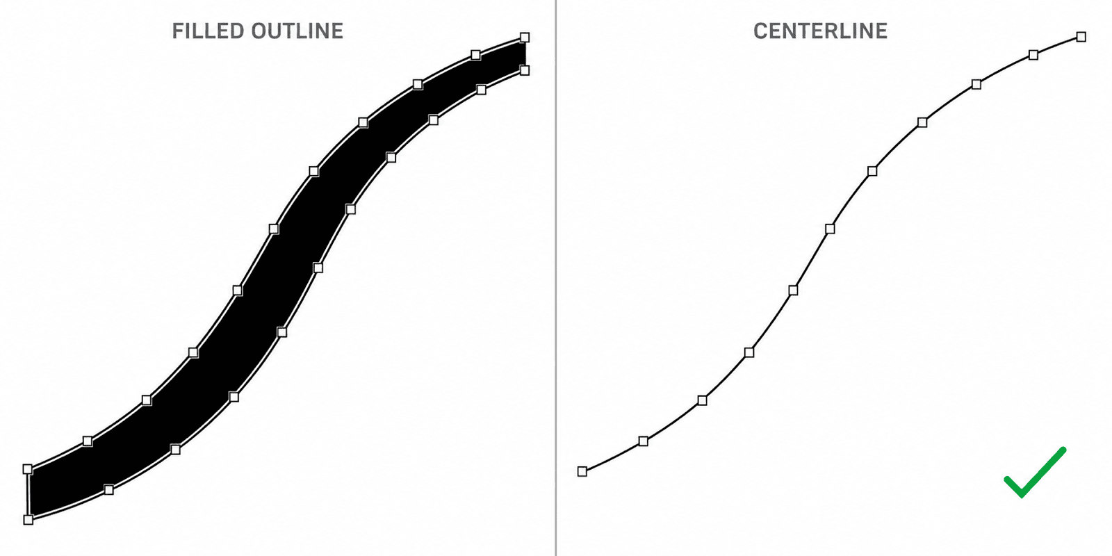 Left: a filled-outline trace turns one drawn line into two contours around a black band. Right: a centerline trace reconstructs it as a single stroke path.
That doubling is invisible at page zoom and disastrous the moment you edit:
- Changing "line weight" means reshaping two contours instead of adjusting one stroke width.
- Node counts explode, so files get heavy and snapping in CAD becomes unreliable.
- Imported into DXF, the double contours read as two separate entities per line — dimensioning and trimming stop making sense.
- Print reduction can leave a visible white core inside lines that were supposed to be solid black.
Centerline vectorization works the other way around: it estimates the skeleton running through each dark band and rebuilds it as one stroke path with a stroke width. That matches how a patent drawing was made in the first place — a pen or a CAD polyline — which is why centerline output stays editable. One drawn line, one path. That is the entire difference, and it is the property to check before trusting any vectorization tool with a drawing set.
Which inputs vectorize well
Vectorization reconstructs lines that already exist. The best inputs are images that are already line art:
| Input | Vectorize directly? | Notes |
|---|---|---|
| Scanned patent drawings (own archives, expired filings) | Yes | Deskew and clean specks first if the scan is rough |
| Flattened PNG/TIFF line art from old projects | Yes | The most common case: the source file is gone, only the export survives |
| AI-generated patent line art delivered as PNG | Yes | Clean black-on-white input converts almost losslessly |
| CAD screenshots | Mostly | Crop UI chrome; anti-aliased thin lines may need a higher-resolution capture |
| Product photos and 3D renders | No | No lines to reconstruct — see the next section |
One practical note on scans: a 300 DPI black-and-white scan is usually enough. What hurts is not resolution but grayscale murk — faint pencil construction lines and JPEG artifacts get reconstructed as real paths. Threshold the scan to clean black-on-white before tracing.
Photos are a two-step job, not a vectorization job
The most common misuse of any vectorizer is feeding it a product photo. A photo has no centerlines to find: edges are gradients, shadows read as shapes, and the tracer returns either a posterized mess or thousands of micro-contours.
The working order is: photo → patent line drawing → vector. Generate a black-and-white line-art figure from the photo first (remove the background, reflections, and shading; add reference numerals at that stage if you need them), and only then vectorize the clean line art. The first step is a drawing problem; the second is a tracing problem. PatentFig AI handles the first step; Vectorize handles the second.
A real conversion, start to finish
Below is a bitmap patent figure — a fictional self-closing door hinge, plain black line art with reference numerals, the kind of file that typically survives when a project's source files are lost:
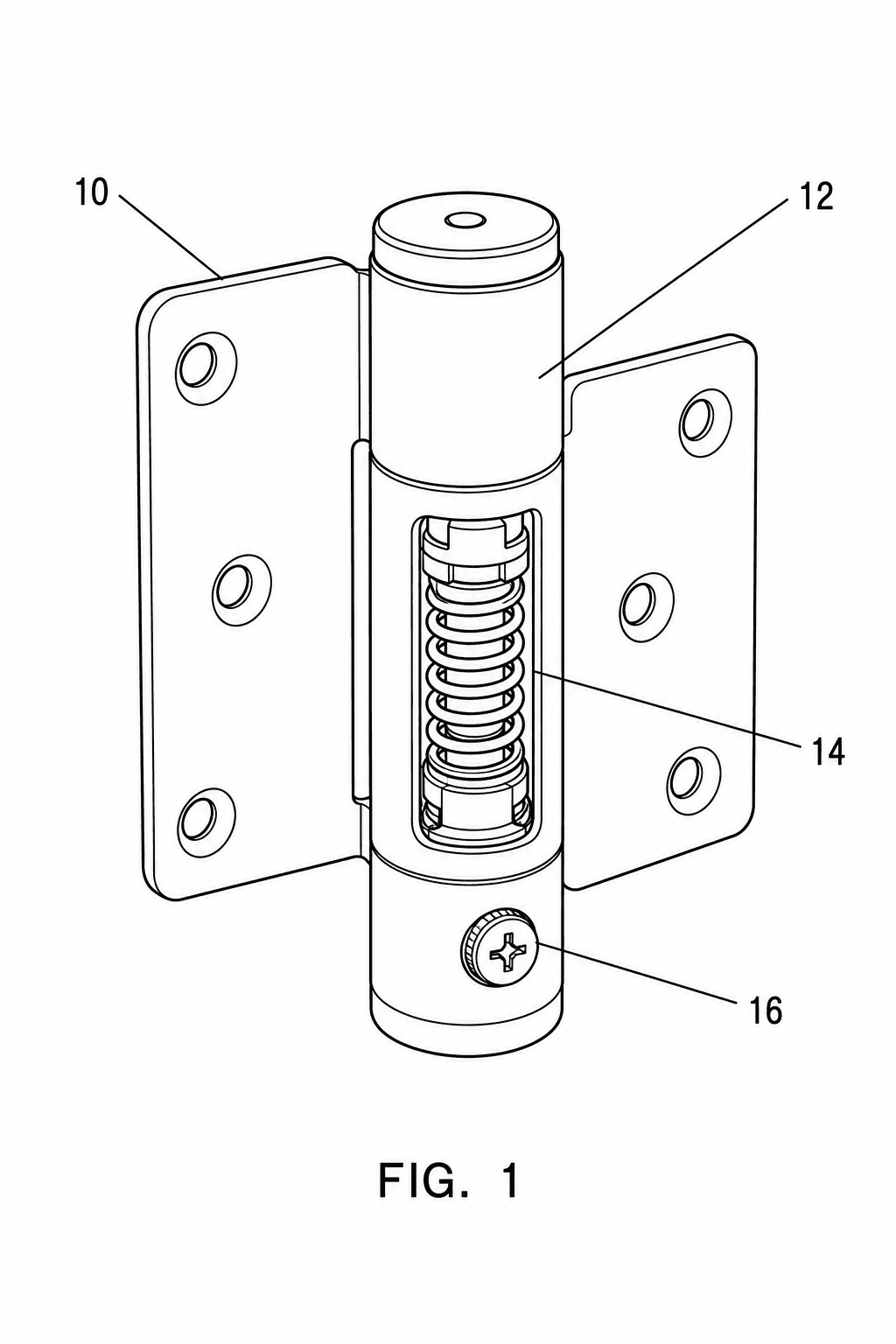 The raster input: solid black lines on white, FIG. label and numerals intact — ideal vectorization material.
And here is the centerline SVG produced from it, embedded directly (open it in a new tab and zoom — the lines stay sharp at any magnification, because they are stroke paths, not pixels):
 The centerline SVG output. Download it, open it in Illustrator or Inkscape, and every line is an individually selectable stroke.
You can download the SVG file itself and inspect it. The numbers from this exact conversion: a 324 KB PNG became an 11 KB SVG containing 119 stroke paths and zero filled shapes — every element is fill="none" with a stroke width, which is precisely what "no double outlines" looks like in the file itself.
SVG, DXF, or vector PDF — pick by destination
The three vector formats are not interchangeable; they map to three different workflows.
- SVG is the editing master. Illustrator, Inkscape, and every modern design tool open it losslessly; strokes, groups, and text stay intact. If you keep exactly one file, keep this one.
- DXF is for CAD round-trips. When the drawing has to go back into SolidWorks, AutoCAD, or Fusion 360 — to be dimensioned, trimmed, or merged with engineering geometry — DXF is the lingua franca. Centerline paths matter doubly here, because CAD treats every path as an entity you snap to.
- Vector PDF is the exchange and review format: attorneys can open it anywhere, it prints predictably, and some filing workflows accept vector PDF directly. It is a poor editing format, so treat it as an output, not a master.
Fixing line weights after conversion
Patent offices want uniform, reproducible line weights, and a fresh trace inherits whatever the raster had. With centerline output this is a five-minute fix, because weight is a stroke property:
- Illustrator: select all → set one stroke weight; use Select > Same > Stroke Weight to normalize groups separately (contours vs. hidden lines vs. leader lines).
- Inkscape: Edit > Select Same > Stroke Style, then set the width once in the Stroke dialog. Enable Scale stroke width with object so later resizing keeps proportions.
- CAD: map the imported layer to a lineweight or polyline global width instead of editing entities one by one.
With a filled-outline trace, none of these work — there are no strokes to adjust. That, more than aesthetics, is why the double-outline problem matters.
Master in vector, file in raster
The end state of this workflow is one editable vector master per figure, and disposable exports from it:
- Vectorize the raster source to centerline SVG (keep DXF alongside it if CAD is involved).
- Normalize line weights and check reference numerals against the specification.
- Archive the SVG/DXF as the master — never flatten it back into the only copy.
- At filing time, export TIFF (300–600 DPI) or vector PDF per the current requirements of your filing system, and run a compliance pass in Figure Checker before anything goes out.
Corrections and office actions then start from paths, not pixels. If your source material is CAD rather than a scan, the CAD to SVG to TIFF workflow covers that route; free drawing-sheet templates and a pre-filing checklist are on the resources page.
Ready to unfreeze a drawing set? Vectorize your patent figures into editable SVG, DXF, or vector PDF.
Author

Categories
More Posts
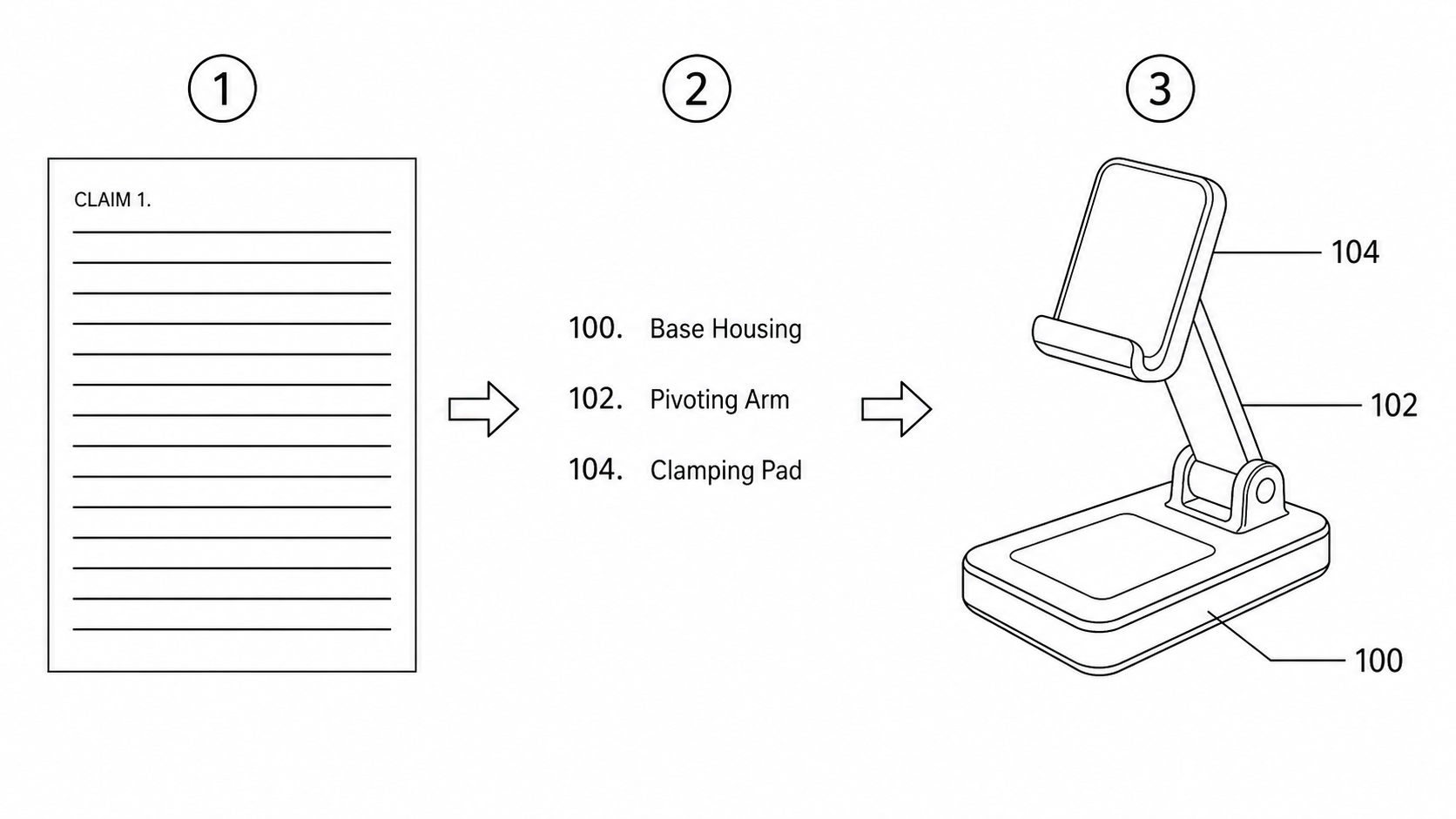
From Patent Claims to Figures: Turning Claim and Specification Text into Drawings
A practical workflow to turn patent claim and specification text into compliant figures: extract components, assign consistent reference numerals, and generate filing-ready drawings.
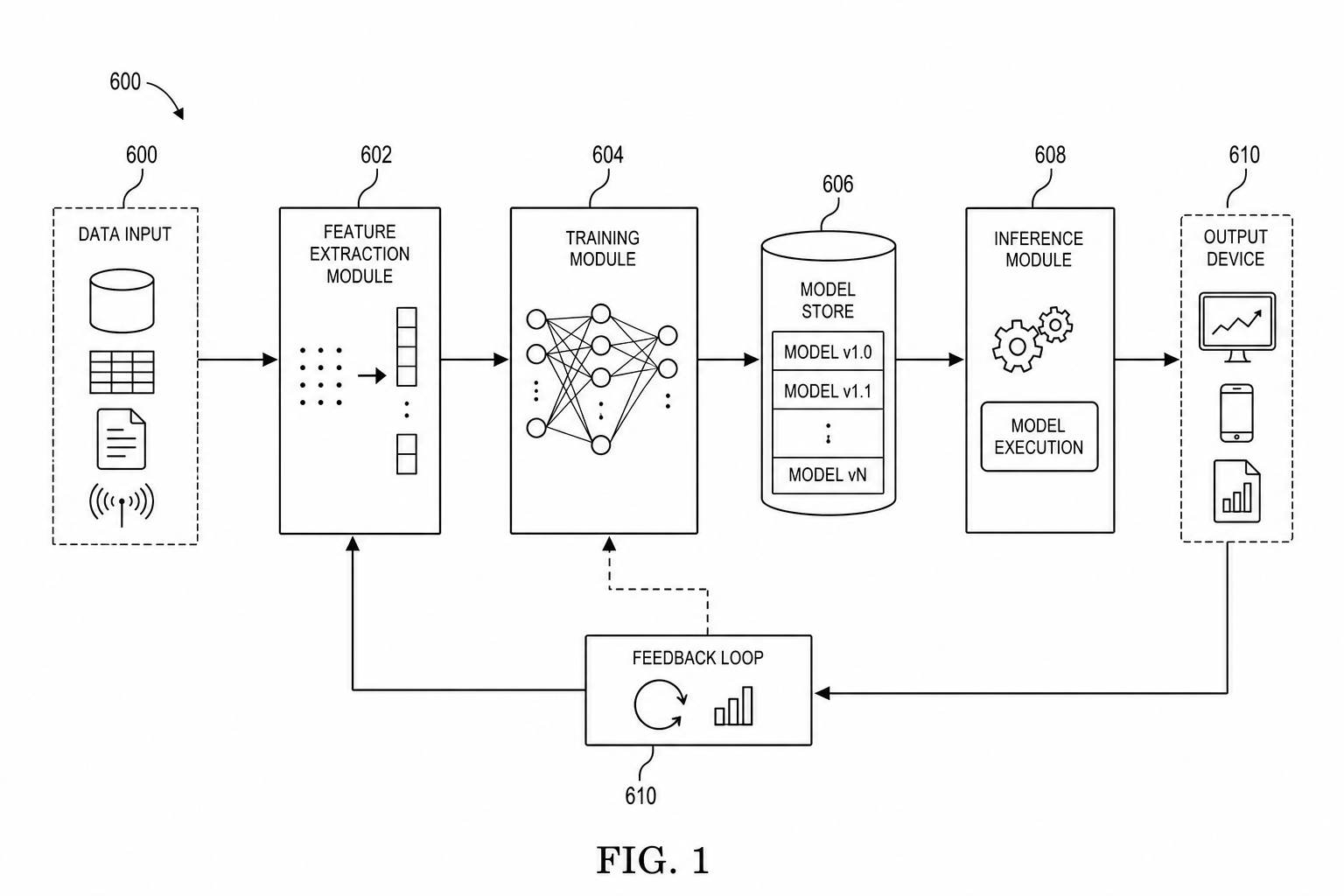
AI/ML Patent Diagrams: Model Pipeline, Training Flow, and Inference System
Create clearer AI and machine learning patent diagrams for model pipelines, training workflows, inference systems, RAG architectures, and agent workflows.
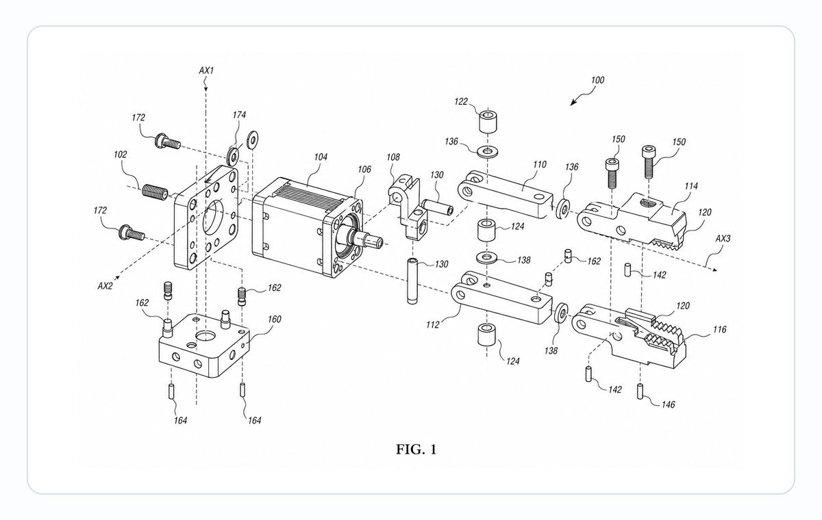
Exploded View Patent Drawing Workflow: Parts, Spacing, Callouts, and Review
Plan exploded view patent drawings with clear part order, spacing, leader lines, reference numerals, and pre-export review.
Newsletter
Join the community
Subscribe to our newsletter for the latest news and updates