
Black-and-White Patent Line Art: Reference Numerals, Lead Lines, and What Examiners Check
How patent figures must be pure black-and-white line art, where reference numerals belong, which lead-line styles pass, and the USPTO 37 CFR §1.84 and CNIPA rejections to avoid.
TL;DR: A patent figure is a legal document drawn in black ink, not an illustration. The rules are narrow and unforgiving: pure black-and-white line art, a pure white background, no color and no gray shading, reference numerals placed outside the part and tied to it by lead lines, and the same number for the same feature in every figure. This post walks through the line-art requirement, lead-line styles, and the specific objections USPTO and CNIPA examiners raise — then gives you a pre-filing checklist.
Most figure rejections are not about whether the drawing is good — they are about whether it is compliant. An examiner is not grading your draftsmanship; they check a small set of formal rules and flag anything that fails. Knowing which rules they check, and why each exists, turns drawing review from guesswork into a checklist.
Run a draft set through the figure checker before you file, or review the full patent drawing requirements for your office.
Why Patent Figures Must Be Black-and-White Line Art
The most fundamental rule is that a utility patent drawing is black-and-white line art on a pure white background. Under USPTO 37 CFR §1.84(a)(1), drawings must be in black ink, with lines that are durable, uniformly thick, clean, and well-defined. No continuous-tone gray, no fill colors, no photographic texture, no anti-aliased softness around edges.
This is not an aesthetic preference. Patents are reproduced, scanned, and printed at small sizes across many systems, some decades old. A drawing that survives all of that has to be bilevel — every pixel is either black or white, nothing in between. The moment you introduce gray, the reproduction system has to guess how to render it, and detail collapses.
A few consequences follow directly from this:
- No color. Color drawings are accepted at the USPTO only by petition under §1.84(a)(2), with a fee and a justification that color is the only practical way to disclose the subject matter. For the overwhelming majority of mechanical, electrical, and software applications, color is simply not allowed.
- No gray shading or gradients. You cannot model a curved surface with a soft gray gradient the way a product render would. Surface shading, where genuinely needed, is done with line work — oblique hatching, or stippling (fields of dots) — not with continuous tone.
- Pure white background. No off-white paper texture, no drop shadows, no subtle vignettes. The background is white, full stop.
- Solid black line work, consistent weight. Visible edges are solid lines of uniform thickness; hidden edges are broken (dashed) lines. Centerlines, section lines, and projection lines each have their own conventional style, but all are crisp black strokes.
CNIPA applies the same logic. Chinese practice requires drawings to be made with uniform, clearly drawn black lines, prohibits shading by gray tone, and disallows color in the ordinary case. If you are filing in both jurisdictions, a clean bilevel master serves both — which is the whole point of building figures to the strict standard from the start.
Shading the right way
When you genuinely need to convey a curved or contoured surface, use the line-art techniques the offices accept:
- Hatching — evenly spaced parallel oblique lines, used both for surface shading and (at a steeper, regular angle) to indicate sectioned material in a cross-section view.
- Stippling — fields of dots, denser where the surface turns away from the viewer, sparser where it faces the light.
Both render cleanly as black-and-white; a gradient does not. If your source is a 3D render or a photo, convert it to true line art before filing.
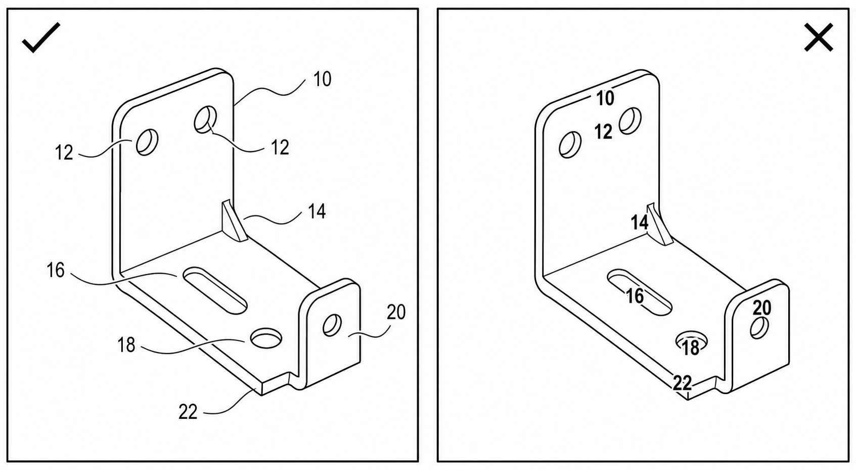
Reference Numerals: Outside the Part, Never On It
Every feature you discuss in the claims and specification needs a reference numeral in the drawings, and the placement of that numeral is one of the things examiners check most reliably.
The rule: reference numerals are placed outside the part, in the surrounding white space, and connected to the feature by a lead line (also called a leader line). The numeral floats clear of the drawing; the lead line does the pointing.
What this means in practice:
- Numerals do not overlap line work. A numeral sitting on top of an edge, a hatched area, or another numeral is an objection. After the figure is reduced for printing, an overlapping numeral becomes unreadable. Keep a clear margin of white around every character.
- Numerals are oriented upright. They read horizontally, the same way up as the page (with the usual exception that numerals on a figure rotated 90 degrees follow the figure's orientation). They are not slanted to follow a curve.
- Numerals are large enough to survive reduction. The USPTO calls for reference characters at least 0.32 cm (1/8 inch) high. Anything smaller risks becoming a smudge.
- One feature, one number — everywhere. The same component gets the same numeral in every figure in which it appears, and a number, once assigned to a feature, is never reused for a different feature anywhere in the application.
The figure above shows the contrast: a numeral set cleanly in the white space with a short lead line to the part (good) versus a numeral crowded onto the line work or left floating with no lead line at all (bad).
Lead-Line Styles and When to Use Each
The lead line is the small line connecting a reference numeral to the feature it identifies. There are three conventional, accepted styles, and choosing the right one removes ambiguity about what the number refers to.
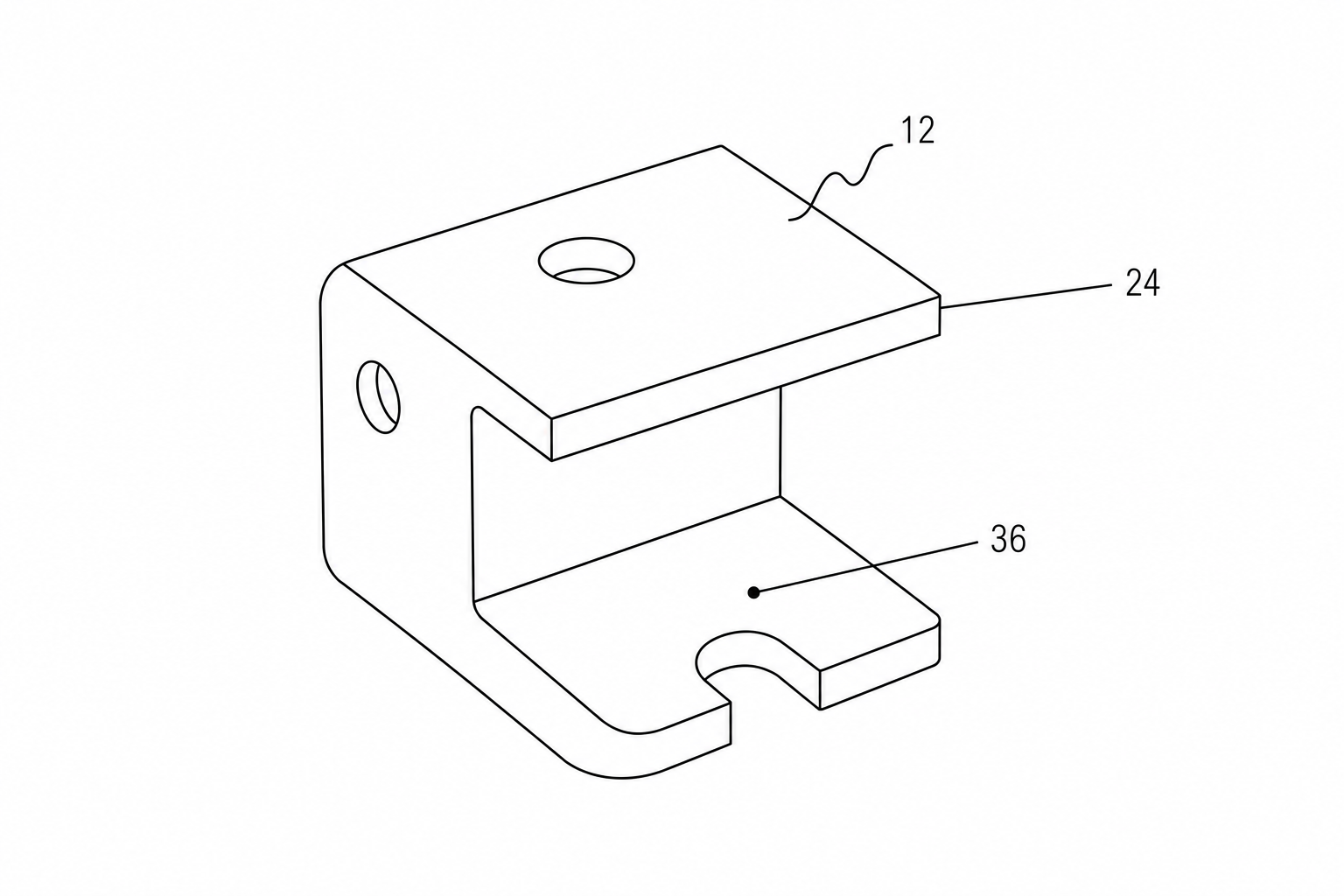
Straight lead line to an edge
A straight line running from the numeral to the edge or outline of the part. This is the default for pointing at a specific, definite feature whose boundary is visible. The line touches the edge and stops; it does not cross into the part.
Straight lead line with an arrowhead to a surface
When the numeral refers to a surface that the lead line has to land on (rather than an edge it can touch), terminate the lead line with an arrowhead pointing at that surface. The arrowhead signals "this surface," distinguishing the lead line from a dimension line.
Squiggly (freehand) lead line for a whole part or region
A squiggly lead line — a short freehand wavy stroke — is used when the numeral refers to the entire part, an assembly, or a general area rather than one precise point. Because it is visibly different from any straight construction line, it cannot be mistaken for a section line, a centerline, or a dimension. Use it whenever the reference is to a region rather than a single edge or surface.
A few rules apply to all lead lines:
- They are as short as practical and do not cross one another where it can be avoided.
- They are the same black weight as the line art (typically the thinner projection-line stroke), so they read as auxiliary, not as structure.
- The numeral sits at the outer end of the lead line, in clear space.
What USPTO and CNIPA Examiners Actually Reject
Drawing objections cluster around a predictable set of issues. These are the ones to scan for before filing:
- Color or gray shading. Any continuous-tone gray, color fill, or photographic gradient. This includes screenshots and 3D renders dropped in without conversion to line art. Solution: convert to true bilevel black-and-white line art with hatching or stippling for any needed shading.
- Non-white or textured background. Off-white scans, paper grain, drop shadows, or background fills. The background must be pure white.
- Numerals overlapping line work. Reference numerals sitting on top of edges, hatching, or other numerals, so they are not clearly legible. The numeral must be outside the part with a clear white margin.
- Missing lead lines. A numeral floating near a part with nothing connecting it, leaving the feature it points to ambiguous.
- Missing reference numerals. A feature discussed in the specification with no corresponding numeral in any figure — or a numeral in the figures that never appears in the specification. The drawings and the written description must match exactly.
- Duplicated or inconsistent numerals. The same number used for two different features, or the same feature carrying different numbers in different figures. This is among the most common objections and the easiest to introduce when figures are drawn or edited separately.
- Inconsistent numerals across figures. A part labeled 12 in Figure 1 and 120 in Figure 3 by accident. Cross-figure consistency is checked across the whole set, not figure by figure.
- Line-weight and quality problems. Lines too faint, too thin, broken where they should be solid, or non-uniform in weight; anti-aliased (fuzzy) edges from a low-quality raster export.
- Numerals too small. Below the minimum character height, so they vanish on reduction.
CNIPA's objections overlap heavily: uniform line weight, no gray-tone shading, no color, clean drawing, and reference signs that are not used unless described in the text and that denote the same feature consistently throughout. The takeaway: one strict, well-built drawing set clears both offices, while a sloppy set fails both.
Pre-Filing Checklist
Run every drawing set through this before you file:
- All line work is solid black on a pure white background — no color, no gray, no gradients, no textures.
- Drawing is bilevel at filing resolution; edges are crisp, not anti-aliased or fuzzy.
- Surface shading, if any, uses hatching or stippling, never continuous tone.
- Every reference numeral sits outside the part, in clear white space, with a margin around each character.
- No numeral overlaps line work or another numeral.
- Every numeral connects to its feature with an appropriate lead line (straight to edge, arrowhead to surface, squiggly to whole-part/region).
- Numerals are upright and meet the minimum height (≥ 0.32 cm at the USPTO).
- Same feature, same number in every figure; no number reused for a different feature.
- Every numeral in the figures appears in the specification, and vice versa.
- Line weights are uniform; visible edges solid, hidden edges dashed, section lines hatched correctly.
- Each figure is labeled (FIG. 1, FIG. 2, …) and numbered consecutively.
For the office-specific details — sheet sizes, margins, view labeling, and the §1.84 subsections that govern each — keep the patent drawing requirements reference open while you review, and validate the final files with the USPTO patent drawing checker.
How PatentFig AI Helps
PatentFig AI generates patent figures as black-and-white line art from the start — clean strokes, uniform line weight, and a pure white background, so you are not retrofitting compliance onto a color render. You can produce multi-view sets and flowcharts, convert, enhance, or vectorize existing artwork into filing-ready line art, and use chat-to-modify editing to add, move, or renumber reference numerals and adjust lead lines without redrawing. The built-in figure checker flags numeral placement, missing or duplicated numerals, shading, and background problems before they reach an examiner.
Ready to build a compliant drawing set? Open the patent drawing generator and start from a description, a sketch, or a CAD export — then run it through the checker before you file.
Author

Categories
More Posts

How to Respond to a USPTO Drawing Objection: Deadlines, Replacement Sheets, and a Same-Day Fix Workflow
Got a USPTO drawing objection? Learn the difference between a Notice to File Corrected Application Papers and an Office Action objection, the six most common 37 CFR 1.84 defects, and how to file compliant replacement sheets — often the same day.

Common Patent Drawing Mistakes That Slow Down Filing
The recurring failure modes in patent drawings — line weight, numerals, views, color mode, extraneous matter — with the rule that catches each and the fix that ships fastest.

How to Check Patent Drawing Compliance Before Filing
A practical pre-filing compliance check for patent drawings: sheet, lines, numerals, views, formats, export. Per-office quirks for USPTO, EPO, PCT, CNIPA, JPO, KIPO.
Newsletter
Join the community
Subscribe to our newsletter for the latest news and updates