
How to Turn Software Architecture Into Patent Flowcharts
Turn software architecture into USPTO-compliant patent flowcharts with AI. Method steps, system diagrams, and Section 112 safeguards in one workflow.
TL;DR: Translate the architecture into two figure layers: a system block diagram supporting apparatus claims and method-step flowcharts supporting process claims, with every box and decision traceable to claim language. AI generation handles the USPTO line-art conventions — monochrome line work, numbered steps, clean terminators — while you own the mapping from code to claims.
Automating Patent Flowcharts: From System Architectures to Method Steps
In the world of software patenting, a picture isn't just worth a thousand words—it’s often the difference between an issued patent and a Section 112 rejection. For technical founders and patent practitioners, the challenge lies in translating abstract code and complex cloud environments into the rigid, formal language of USPTO-compliant drawings.
Whether you are documenting a machine learning pipeline or a distributed ledger architecture, flowcharts and system diagrams are the bedrock of your disclosure.
Need compliant patent figures faster? Try PatentFig AI in the generator.
For system overviews, start with the patent block diagram generator. For model training, inference, RAG, and agent workflows, use the AI / ML patent diagram generator. Keep ordered method steps in the patent flowchart generator so architecture and sequence do not collapse into one overloaded figure.
1. The Importance of Procedural Figures in Software IP
The USPTO requires that a patent application satisfy the "written description" and "enablement" requirements. This means your filing must provide enough detail for a person of ordinary skill in the art (PHOSITA) to replicate the invention without undue experimentation.
For software, text descriptions of algorithms are rarely sufficient on their own. Flowcharts serve as the roadmap for the logic, while system diagrams define the physical or functional environment where that logic lives. Without these procedural figures, examiners often find the "metes and bounds" of the invention too vague, leading to costly Office Actions.
By visualizing the "how" and the "where," you create a structural framework that anchors your claims.
2. Designing Robust System Architecture Diagrams
Before you can explain what the software does, you must show where it happens. A robust system architecture diagram (usually Figure 1 in a software patent) visualizes the hardware-software interactions.
When designing these technical schematics, focus on these core components:
- The Computing Environment: Is it a client-server model, a mobile device interacting with a cloud API, or an edge computing node?
- Functional Entities: Break down your system into discrete modules—such as an "Inference Engine," a "Data Pre-processing Unit," or a "Secure Vault."
- Data Flow Paths: Use directed arrows to show how information moves between sensors, databases, and processors.
Using PatentFig AI, you can move from a high-level technical summary to a structured schematic that identifies these entities with the formal precision required for patent drawings, ensuring that every block in your diagram corresponds to a specific element in your written specification.
3. Streamlining Method-Step Flowcharts with AI
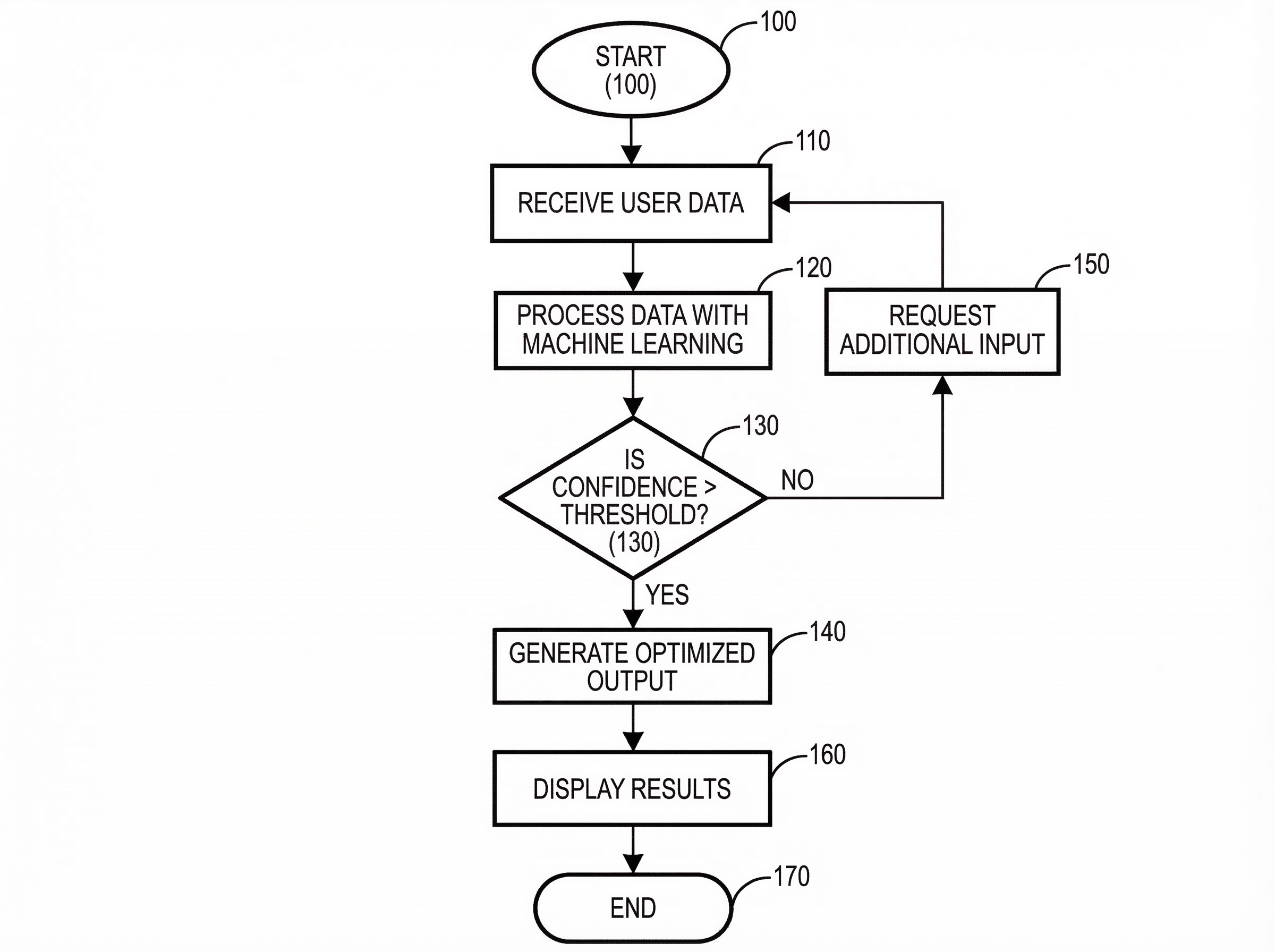
Method-step flowcharts are the primary way to claim a "process" in software. These diagrams use standard symbols—ovals for start/end points, rectangles for process steps, and diamonds for decision logic—to track the execution of an algorithm.
The traditional workflow for creating these is tedious: a founder writes a technical memo, an attorney drafts the steps, and an illustrator spends hours in Visio or AutoCAD trying to make it look "patent-formal."
PatentFig AI streamlines this by leveraging AI to transform raw technical logic into a formal process flow. By inputting your method descriptions, the tool automatically organizes the sequence of operations into a logical hierarchy, ensuring the flow is linear and easy for an examiner to follow.
This automation allows for rapid iteration. If the engineering team tweaks the logic during the drafting phase, the flowchart can be updated in seconds rather than sent back to a third-party drawing service for a multi-day turnaround.
4. USPTO Best Practices for Line-Art Figures
Creating a flowchart is one thing; making it USPTO-compliant is another. To avoid "Notice to File Corrected Application Papers," keep these technical tips in mind:
- Reference Numerals: Every box, arrow, and component must have a unique reference numeral (e.g., Module 102, Step 204). These must be consistently referenced in the written description.
- Line Weights and Clarity: Use high-contrast, black-and-white line art. Grayscale, shadows, and color are generally not permitted. Lines should be uniform and thick enough to remain legible when reduced in size.
- Text Size: Ensure that the text inside your flowchart boxes is large enough to be readable. If a step is too long, it’s better to break it into two boxes or use a broader functional description.
- Avoid "Busy" Diagrams: If a system is too complex, break it into multiple figures (e.g., FIG. 1A and FIG. 1B) rather than cramming fifty elements into one page.
For international filing programs, compare this workflow with:
- Patent Drawing Requirements by Office
- PCT patent drawing requirements
- KIPO patent drawing requirements
5. Optimizing Your Patent Filing Workflow
The goal of using AI-driven tools like PatentFig AI is to bridge the gap between technical disclosure and the final filing. For software founders, this means spending less time explaining "how the cloud works" to a drafter and more time defining the unique logic of the invention.
By automating the generation of method steps and system architectures:
- Consistency is Guaranteed: The AI ensures that the terminology in your figures matches the technical disclosure.
- Cycle Times are Slashed: You can generate a full set of formal figures in the time it usually takes to schedule a kickoff call with a human illustrator.
- Cost Efficiency: Reducing the manual labor involved in technical illustrations allows for a more scalable IP strategy, especially for startups with large feature sets.
In the competitive landscape of software IP, the ability to clearly visualize your innovation is a strategic advantage. By leveraging structured AI workflows, you can ensure your flowcharts are as robust and sophisticated as the code they represent.
Create Patent Figures Faster
Ready to turn rough sketches, CAD screenshots, or prompts into patent-ready visuals? Open the PatentFig AI generator.
Next step: Open the generator and try this workflow with your own source material — or browse patent drawing examples for a starting point.
Author

Categories
More Posts

Software Patent Diagrams: Architecture, Flowcharts, UI Screens, and AI Systems
Plan software patent figure sets across architecture diagrams, method flowcharts, UI figures, AI pipelines, and export review.

Patent Block Diagram Examples for Software, Hardware, and AI Systems
How to structure patent block diagrams for software systems, hardware products, AI workflows, networked devices, and platform inventions.

AI/ML Patent Diagrams: Model Pipeline, Training Flow, and Inference System
Create clearer AI and machine learning patent diagrams for model pipelines, training workflows, inference systems, RAG architectures, and agent workflows.
Newsletter
Join the community
Subscribe to our newsletter for the latest news and updates