")
Design Patent Drawings — Broken Lines, Shading & Required Views (2026)
Design patent drawings explained: broken vs solid lines, shading conventions, all 7 required views. USPTO-ready examples included.
TL;DR: In a design patent the drawings are the claim: solid lines define what you protect, broken lines mark unclaimed environment or context, and surface shading (parallel lines or stippling) shows 3D contour. Plan for all seven standard views — front, rear, left, right, top, bottom, and perspective — with perfectly consistent line weights and features across them; internal inconsistency between views is the top driver of §112 rejections.
Mastering Design Patent Drawings: Broken Lines, Surface Shading, and Essential Views
In the world of intellectual property, a design patent is only as strong as its drawings. Unlike utility patents, where the written claims define the legal boundaries of an invention, a design patent’s scope is dictated almost entirely by its visual representation. In the eyes of the USPTO, the lines, shading, and perspectives are the claim.
For patent attorneys and industrial designers, achieving "full disclosure" while maintaining strategic flexibility is a delicate balancing act. High-quality drawings don’t just satisfy examiner requirements—they prevent future litigation loopholes and ensure the design is protected against infringers.
Need compliant patent figures faster? Try PatentFig AI in the generator.
For a product-focused workflow that keeps broken lines, shading, and multi-view consistency together, use the design patent drawing software page as the companion workflow.
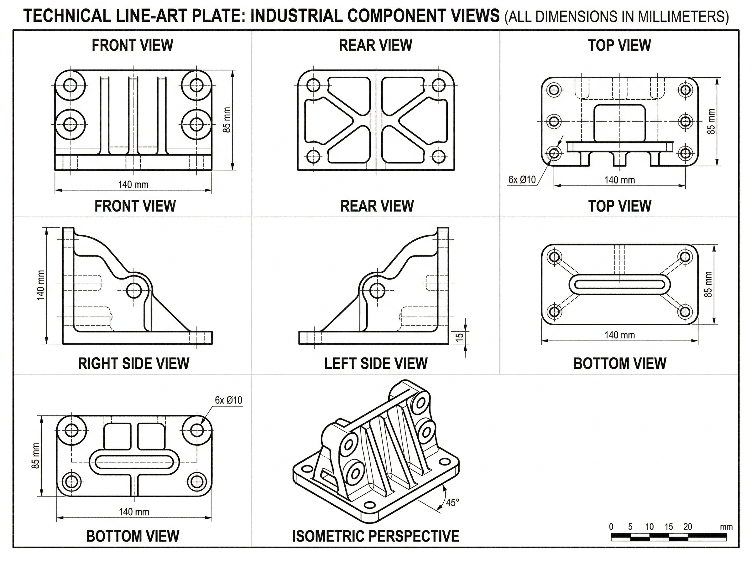
The Seven Required Views for Complete Disclosure
To satisfy the USPTO’s requirement for a complete disclosure of the three-dimensional appearance of a design, you typically need to provide seven standard views. Missing a single angle can lead to a "New Matter" rejection later in the prosecution process, as you cannot add details that weren't present in the original filing.
The essential views include:
- Perspective: A three-dimensional view that shows the depth and volume of the object.
- Front: A direct elevation view of the face.
- Rear: The opposite side of the front view.
- Left Side: A profile view.
- Right Side: The opposite profile view.
- Top: A plan view from above.
- Bottom: A plan view from below.
While some views may be omitted if they are mirror images or plain and unornamented (with a proper statement in the description), providing all seven is the safest path to a smooth examination.
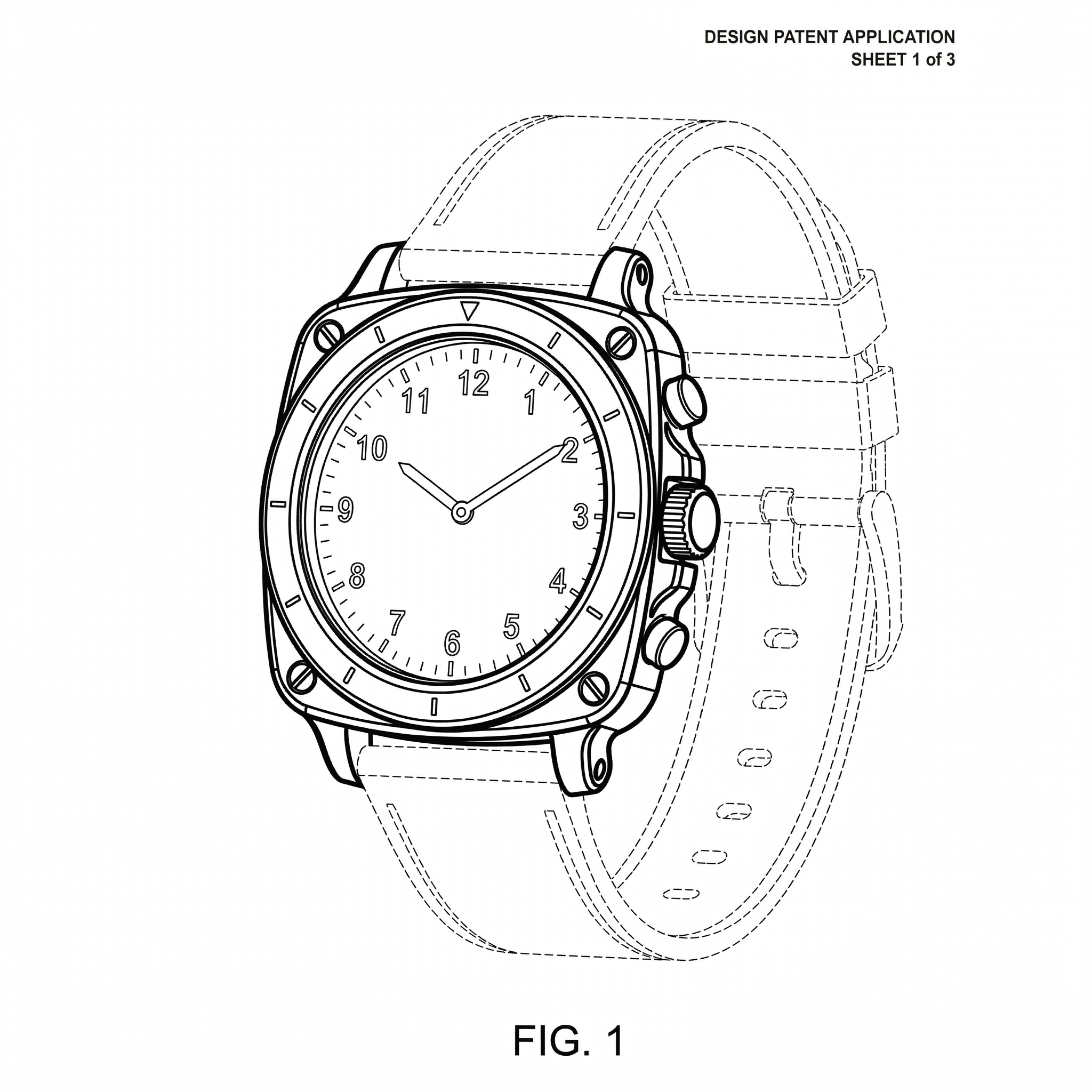
Mastering Broken Lines: Defining Claim Scope
Broken lines (dashed or dotted lines) are perhaps the most powerful strategic tool in a design patent application. They allow the applicant to show the environment in which the design exists without actually claiming that environment as part of the protected design.
There are three primary ways to use broken lines effectively:
- Unclaimed Subject Matter: Use broken lines to show parts of an article that are not part of the design you want to protect. For example, if you designed a novel charging port for a smartphone, you would draw the port in solid lines and the rest of the phone in broken lines.
- Environmental Context: These show how the design is used. A tractor attachment might be shown in solid lines, while the tractor itself is in broken lines to provide scale and context.
- Boundary Lines: A "phantom" line can define a boundary between a claimed surface and an unclaimed surface when no physical edge exists.
The strategic takeaway: By using broken lines to exclude non-essential elements, you broaden the scope of your patent, making it harder for competitors to "design around" your claim by simply changing the unclaimed parts.
Surface Shading: Communicating Contour and Materiality
The USPTO requires surface shading to clearly show the character and contour of all surfaces of any three-dimensional aspect of the design. Without proper shading, a drawing may look flat, making it difficult for an examiner to distinguish between a concave surface, a convex surface, or a flat plane.
Standard technical guidelines include:
- Linear Stippling and Contour Shading: Use thin, parallel lines to indicate curvature. Lines should be closer together in shadowed areas and further apart in highlighted areas.
- Transparency: Indicated by light, oblique (diagonal) strokes. This is critical for designs involving glass, clear plastic, or liquid.
- High-Polish Finishes: Specialized shading patterns can represent mirrored or metallic surfaces without cluttering the drawing.
Effective shading should provide clarity, not confusion. Over-shading can obscure the design's edges, leading to "indefinite" rejections.
If you are adapting design-oriented figures for multiple filing paths, compare this USPTO-focused guide with:
- Patent Drawing Requirements by Office
- EPO patent drawing requirements
- JPO patent drawing requirements
Common Rejections and How to Avoid Them
Even seasoned IP operations teams run into USPTO 112(a) and 112(b) rejections. Most of these stem from "internal inconsistency."
Common pitfalls include:
- Inconsistent Line Weights: A line that appears as a heavy solid line in the front view but a thin broken line in the perspective view will trigger an immediate rejection.
- Missing Features: If the top view shows a button that doesn't appear in the side profile, the disclosure is considered incomplete.
- Vague Contours: If the examiner cannot tell if a surface is rounded or angled due to lack of shading, the design is deemed "indefinite."
To avoid these, perform a "line-by-line" audit across all seven views before filing. Every edge, vertex, and shadow must correlate perfectly across the entire set.
Automating Design Patent Figures with AI
Traditionally, converting a high-fidelity 3D CAD model into USPTO-compliant line art was a manual, multi-day process involving specialized draftsmen. This often created a bottleneck in the R&D-to-filing pipeline.
PatentFig AI changes this workflow by automating the generation of design patent figures. By utilizing AI trained on USPTO standards, PatentFig AI can take 3D models or even detailed sketches and instantly generate the seven required views with:
- Perfectly consistent line weights across all angles.
- Automatic application of compliant surface shading and stippling.
- Strategic toggle for solid vs. broken lines to define claim scope.
For founders and IP teams, this reduces the drafting cycle from days to minutes, allowing for faster filing and lower prosecution costs. By removing the human error inherent in manual tracing, PatentFig AI ensures that the consistency required to avoid 112 rejections is built directly into the file.
Create Patent Figures Faster
Ready to turn rough sketches, CAD screenshots, or prompts into patent-ready visuals? Open the PatentFig AI generator.
Next step: Browse 25 patent drawing examples by category — or open the generator and adapt the closest one to your invention.
Author

Categories
More Posts

Utility Patent Drawings vs Design Patent Drawings: Which Figures You Need
Compare utility patent drawings and design patent drawings: figure purpose, views, line rules, broken lines, reference numerals, and when to use each workflow.

Medical Device Patent Figures: Exploded Views, Cross-Sections, and Use States
Plan medical device patent figures for cartridges, wearables, patches, sensors, surgical tools, exploded views, cross-sections, and use states.

Mechanical Patent Drawing Examples: Bolts, Washers, Flanges, Hinges, and Cross-Sections
Practical mechanical patent drawing examples for bolts, washers, flanges, hinges, exploded views, cross-sections, labels, and revision workflows.
Newsletter
Join the community
Subscribe to our newsletter for the latest news and updates